Categories: Featured Articles » Practical Electronics
Number of views: 63740
Comments on the article: 0
Homemade dimmers. Part Four Thyristor Practical Devices
 The basis of dimmers and power regulators are, as a rule, thyristors and triacs. The operation of these semiconductor devices was described in the previous three parts of the article, and now you can get acquainted with the device of some practical devices on thyristors. All circuits to be considered use the phase control principle described at the end. third part of the article.
First, let's get acquainted with fairly simple schemes containing a small amount of detail, and at least therefore, the most affordable for repetition in amateur conditions. However, the schemes can be more complex, but the algorithm for their work is still the same - the brightness of the light source is adjusted. Sometimes there are schemes combining the actual dimmer and twilight switchor a scheme for smoothly turning on the lamp. But first, the simplest schemes.
In order not to return to the previous part of the article each time, perhaps this insert the image again at this point in the text.
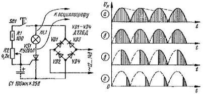
Picture 1. Timing diagrams of a phase power regulator
The vertical shading corresponds to the on state of the thyristor, and the power supplied to the load is proportional to the area of the shaded areas.
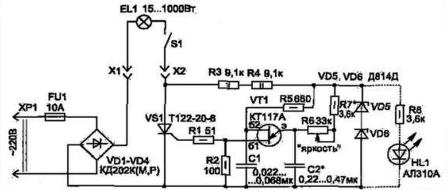
On the image 2 shows a simple dimmer circuit that only allows you to adjust lamp brightnesswithout any additional features.
Picture 2. Simple dimmer
The mains voltage through the fuse FU1 is supplied to rectifier bridge VD1 - VD4, into the diagonal of which DC thyristor VS1 and lamp EL1 are connected. In some schemes, the lamp is included in the diagonal of the bridge for alternating current, but this is not important. The thyristor is applied quite powerful, which allows you to control the load up to 1000W, as, and is indicated on the circuit diagram. If such power is not required, then the thyristor can be replaced by another, for example, from the KU202M series, which will allow you to control the brightness of a lamp with a power of at least 500W.
The controller uses the phase control method: pulses are received on the thyristor control electrode, which are phase shifted relative to the voltage at the anode. The circuit that generates control pulses is built on a single-junction dual-base transistor VT1 type KT117A. This transistor has no foreign analogues.
The main purpose of this transistor is to build the simplest generators - tweeters, triggering circuits for pulsed power supplies (used in power supplies of 3USTST series televisions), as well as control pulse generators in phase control circuits similar to that considered. This generator works as follows.
The rectified mains voltage through resistors R3, R4 is stabilized by series-connected Zener diodes VD5 VD6 at a level of about 22 - 25V, which depends on specific instances of zener diodes. This voltage, by the way, is pulsating, corresponds to diagram a) in the figure 1.
This ripple voltage through the resistors R6, R7 charges the capacitor C2. As soon as the voltage across it reaches the opening value of the single-junction transistor VT1, it opens and the capacitor C1 is discharged through its transition B2 - B1, resistors R1, R2 and UE of thyristor VS1, as a result of which a control pulse is formed, the thyristor opens and the current passes through the load. When the rectified ripple voltage passes through zero, the thyristor closes and remains closed until the next opening pulse arrives.
The charge rate of capacitor C2 is regulated by resistor R7.When its resistance is minimal (the engine is brought out to the left according to the diagram), the charge speed is maximum, the thyristor will open at the very beginning of the half-cycle, passing the maximum power into the load. When the resistor R7 engine moves to the right according to the scheme, the charge speed of the capacitor C2 decreases, therefore, the pulse controlling the thyristor VS1 will be formed later. Since this regulation is phase, and the phase is measured by angular units - radians, they say that the pulse is formed at a certain angle, in this case later than at maximum power in the load. This process is shown in the figure. 1 on diagrams b, c, d.
In the diagram, the dashed line shows the LED HL1 and resistor R8. Their purpose is to show that the device is connected to the network, as well as monitoring the health of the lamp, unless, of course, the regulator is set to a minimum. But, in fact, the regulator is quite functional without this addition, or as options will not say now.
Setting up the device is quite simple. With the resistor R6 brought to zero, the resistor R7 is selected so that the brightness of the lamp is maximum. This setting depends on the value of the capacitor C2, the value of which may also require selection within the limits indicated on the diagram.
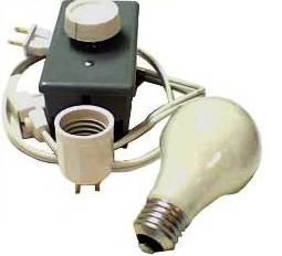
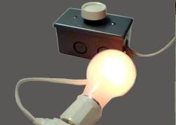
Fig. 3. Homemade dimmer
In the considered circuit, a thyristor is used as a switching element, therefore, in order to be able to regulate both the positive and negative half-waves of the mains voltage, a sufficiently large diode bridge has to be used in the circuit.
If the load power is close to the maximum permissible, then the thyristor, and with it the bridge diodes, will have to be installed on a heat sink - radiator, which further increases the dimensions of the device and the complexity of its manufacture. To get rid of the use of a powerful rectifier bridge, counter-parallel connection of two thyristors is used, which is also not very convenient and technologically advanced.
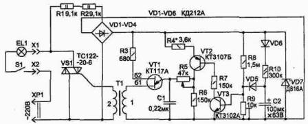
The use of symmetric thyristors - triacs gives much better results: in one case already contains two counter-thyristors connected in parallel. On the image 4 A modified circuit using a triac is shown.
Picture 4. Dimmer on the triac
A slight refinement of the circuit will allow it to slightly reduce its dimensions, while the load power remains the same. The thyristor start-up unit is also made on a single-junction transistor KT117A, only the transistor is loaded on a matching transformer T1. Such a coordination is necessary in order to obtain control pulses without a constant component. This makes it possible to open the triac in both positive and negative half-periods of the mains voltage.
The matching transformer is made on a ferrite ring of size K16 * 10 * 4 of ferrite of the most common brand НМ2000. Winding 1 contains 80, and winding 2 contains 60 turns of PELSHO-0.12 wire. Before winding, the sharp edges of the ring should be blunted with sandpaper or a diamond file to avoid damage to the insulation, and the ring itself should be wrapped with a tape of thin varnish, in extreme cases, adhesive tape.
The rectifier bridge VD1 - VD4 is used only to power the adjustment unit, as well as a new circuit element - the unit for smooth start of the load. Therefore, the diodes in it are low-power, in addition to those indicated on the diagram, 1N4007 can be used, they are suitable for almost all occasions. The soft start assembly is assembled on transistors VT2, VT3.
His work is as follows. When the power is turned on, the capacitor C2 starts charging on the circuit VD6, R10. Through the diode VD5, the voltage across the capacitor C2 begins to open transistors VT3 and VT2. The resistance of the emitter-collector section of the transistor VT2 decreases, so the total resistance of the section R4, VT2, R5 decreases smoothly, and the charging speed of the capacitor C1 also gradually increases, the brightness of the lamp increases.
Read on in the next article.
Continuation of the article: Homemade dimmers. Part 5. A few more simple schemes
Boris Aladyshkin
See also at bgv.electricianexp.com
:

