Categories: Featured Articles » Practical Electronics
Number of views: 67348
Comments on the article: 2
Homemade dimmers. Part two. Thyristor device
 The first part of the article: Homemade dimmers. Types of Thyristors
After the device and use of the dynistor have been considered, it will be easier to understand the device and the operation of the trinistor. However, most often the trinistor is simply called a thyristor, somehow more familiar.
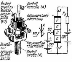
The device triode thyristor (trinistor) shown in figure 1.
In the figure, everything is shown in sufficient detail and as a whole, except perhaps for another building, it reminds dinistor device. The connection diagram of the load and the battery is the same as that of the dinistor.
In both cases, the power source is conventionally shown as a battery in order to see the polarity of the connection. The only new element in this figure is the UE control electrode connected, as already mentioned, to one of the regions of the “layered” semiconductor crystal.
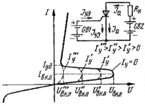
Volt – ampere characteristic of a trinistor shown in Figure 2, and is very similar to the corresponding characteristic of the dinistor.

Figure 1. The device triode thyristor

Figure 2. Volt - ampere characteristic of a trinistor
If we assume that UE is not used as if it did not exist at all, then the trinistor, like a dynistor, will open with a gradual increase in the direct voltage between the anode and cathode. In reference books, this voltage is called Upr - forward voltage.
If, according to the directory, the direct voltage for a particular trinistor is 200V, and we supply all 300 or more to it, then the thyristor will open without any voltage on the control electrode. You need to know about this and always remember, otherwise embarrassing situations are possible: "They installed a new thyristor, but it turned out to be unusable."
If a positive voltage is applied to the control electrode, naturally relative to the cathode, then the thyristor will open much earlier than the forward voltage reaches its limit value. There is a kind of rectification of the ejection of the current-voltage characteristic, which is shown by dashed lines. At a certain point, the characteristic becomes similar to that of a conventional diode, the current through the RE reaches its maximum value and is called the rectification current Iue.
The control electrode is, in fact, igniting: a short pulse of a few microseconds is enough to open the thyristor, then the UE loses its control properties until the trinistor is turned off in one of the available ways. These methods are the same as for the dinistor, they were already mentioned above.
It is impossible to turn off the trinistor by acting on the control electrodealthough, in fairness it must be said that there are lockable thyristors. True, they are very few, and they are not widely used, especially in amateur designs.
Another important point: the load resistance must be such that the current through it is not less than the holding current for this type of thyristor. If, for example, the regulator works normally with a bulb, for example, 60 W, then it is unlikely to work if, instead of such a load, a just a neon bulb is connected.
After such a purely theoretical acquaintance, we can proceed to practical experiments, which allow us to understand and remember using the simplest schemes and techniques, how thyristor works. Well-known folk wisdom already comes into play: it doesn’t reach through the head, it will come through the hands, or in another way: “Do you remember the hands !!!” Very good principle, it helps almost always!
Simple entertaining triac experiments
Thyristor check
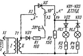
To conduct these experiments will need KN201 or KU202 trinistor with any letter index, the power supply is better if adjustable, several resistors, light bulbs, buttons and connecting wires. The assembly of circuits is best carried out by hinged installation, as will be shown in the figures, of course, with using a soldering iron. The circuit shown in Figure 3 will allow check the thyristor for operability.

Figure 3. Circuit for checking thyristor
The easiest way to assemble such a scheme using transformer TVK-110L1, was used in black and white TVs as an output frame scan. When connected to a 220V network without any alterations on the secondary winding, a voltage of about 25V is obtained, which is sufficient not only for the described experiment, but also for creating low-power power supplies, similar to those Chinese-made network adapters that are sold in stores. If the transformer TVK-110L1 is not available, you can use any with a secondary voltage of 12 - 20V with a power of at least 5W.
Still need the thyristor itself, three semiconductor diode (can be replaced with 1N4007, as the most common at present), a couple of light bulbs for 12V voltage (used in cars to illuminate instrument panels), a button and several resistors. If you can find the lamps for 24V, then the installation of resistors R3 and R4 is not required.
Resistor R2 is designed to provide the required holding current of the thyristor. If you use more powerful lamps, then installing this resistor is not needed. Resistor R1 limits the current in the control electrode circuit.
The method of using the "device" is quite simple. When you turn on the device in the network should not light any of the lamps. When you press the SB1 button while holding it, the HL1 lamp should light up. If this does not happen, then the thyristor malfunction is hidden in the control electrode. If, when you turn on the circuit, both lamps are immediately lit, then the thyristor is simply broken.
By the way, this device can also check diodes: if instead of a thyristor you connect a diode in the polarity indicated on the diagram, then the lamp HL1 will light up, and when the direction of the diode is turned on - HL2.
Here the question may arise: “Why check the diodes in this way when there is a conventional digital tester for this?” The answer to this question will be as follows. There are cases, though rare, but aptly when a tester, even a pointer, shows that the diode is working. And only the “dialing” through the bulb indicates that under the load the diode “breaks”, the bulb does not light up in whatever direction the diode is connected. Just to detect such a defect, the measuring current of the tester is not enough. By the way, such a “dubbing” of a diode through a light bulb can also be made from a constant voltage source.
A little lyrical digression
Those involved in the repair know that it is necessary to check the parts most often when they are soldered into the circuit, and you just have to do this with a tester. And in this situation it is best to use the good old pointer device, for example, type TL4-M.
In the resistance measurement mode, these devices have a greater measuring current than modern digital testers, which allows you to keep the thyristor type KU201, KU202 or the like open. The verification procedure is as follows. Measurement is at the limit *Ω.
First you need to touch the tester probes to the anode and cathode of the thyristor, naturally, observing the polarity. The arrow of the device must not deviate. After that, close, for example, with tweezers the conclusions of the UE and the anode (body). The arrow should deviate to about half the scale, and after the tweezers are removed, remain in the same place. Such a thyristor can be safely installed in any design.
If, after opening the UE circuit, the arrow returns to the starting point of the scale, this indicates that the holding current of the thyristor, even a new one, not soldered, is very large, or a large opening current of the UE, and in some cases this trinistor will not work.
Such the method is suitable for rejecting thyristorsmainly domestic. Imported thyristors, as a rule, open more easily and reliably. The same technique is also suitable for testing symmetric thyristor (triac).
A small but important note: for arrow testers in the resistance measurement mode, the positive probe of the ohmmeter is the one that in the measurement mode of constant voltage is negative. This must be known, and always remembered. Digital testers plus an ohmmeter are in the same place as when measuring DC voltage. Naturally, the digital tester will not be able to carry out the above test.
After the thyristor is checked, you can conduct several simple experiments to practically familiarize yourself with its work. Well, this is just from the category of “but the hands remember.”
Read on in the next article.
Continuation of the article: Homemade dimmers. Part three. How to control a thyristor?
Boris Aladyshkin
See also at bgv.electricianexp.com
:
