Categories: Featured Articles » Practical Electronics
Number of views: 78262
Comments on the article: 1
Homemade dimmers. Part Five Some more simple schemes
Dimmer on an analog of a single junction transistor
The circuit of such a dimmer is shown in Figure 1.
 Despite the absolute dissimilarity of the schemes at first glance, they work almost identically. The brightness of the lamp is controlled by the phase method of controlling the thyristor, however, the load connection is somewhat different.
In the considered circuit, the regulator load, a light bulb, is included in the diagonal of the rectifier bridge for alternating current. The thyristor itself is included in the diagonal by a constant, rectified current. IN previous pattern The bulb itself is also included in this diagonal, but in this case it does not change anything.
On transistors VT1, VT2 assembled a soft start node, which will be described below, but for now, consider the operation of the controller itself. If we mentally draw a vertical line in Figure 1 between the transistor VT2, and the resistors R3 and R4, then everything that turns out to be to the right of this line is actually dimmer.
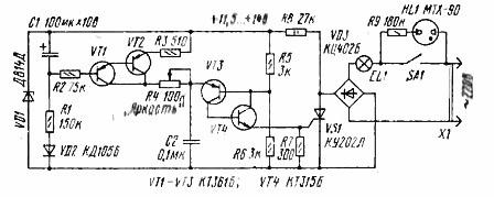
Figure 1. Dimmer on an analog of a single junction transistor
Instead of a single-junction double-base transistor KT117A, its analogue, assembled on transistors VT3, VT4, is used in the triggering pulse generating circuit. If we connect the collector and emitter of transistor VT2 with a jumper wire, then the capacitor C2 will be charged through resistors R3 and R4.
When the voltage across it reaches the opening voltage of the analog of a single-junction transistor, it will open and form a voltage pulse on the UE of the thyristor VS1, which will turn on and the current will flow through the load. The thyristor will be locked in the same way as in the previous circuit at the time the mains voltage passes through zero. Resistor R4 adjusts the brightness, as evidenced by the inscription on the diagram. The maximum brightness will be achieved when the engine of the variable resistor R4 is brought to the extreme left position according to the scheme, the charge speed of the capacitor C2 is maximum.
If the wire jumper between the collector and emitter of the VT2 transistor has been installed, then it should be removed and further research should be continued. The soft start circuit works as follows.
At the time of power-up, capacitor C1 is not yet charged, so the composite transistor VT1 VT2 is closed, and the collector-emitter section of VT2 is large, there is almost an open between resistors R3 and R4, which does not allow charging of the timing capacitor C2.
After turning on the power through the circuit VD1, R1, the oxide capacitor C1 starts charging. The voltage on it begins to increase smoothly, which leads to the gradual opening of the composite transistor VT1 VT2 and the capacitor C2 is gradually charging.
The constant of the charging time of the capacitor C1 is such that the charging process lasts several seconds, the same time there is a slow decrease in the resistance of the collector-emitter section of the transistor VT2, so slow that it looks like a slow rotation of the resistor R4 in the direction of decreasing the resistance: a smooth increase in brightness occurs, which contributes to increase the service life of the incandescent lamp itself.
And in the end, the brightness will be set in accordance with the position of the engine of the resistor R4, at what brightness it was turned off yesterday, at the same brightness it will turn on today. Naturally, after such a start, you can manually adjust the brightness of the lamp if necessary.
In parallel to the network switch SA1, a chain of resistor R9 and a neon lamp HL1 is installed, the purpose of which is to illuminate the switch in a dark room.
Dimmer dimmers
The circuit of such a dimmer is shown in Figure 2.
Figure 2. Dimmer dimmer
As an example of such a dimmer, an industrial circuit can be used that was used in domestic injection molding machines (machines for molding plastic products). In them, of course, it was not a light regulator, it simply controlled the power of electric heaters, being an integral part, in fact, of an output cascade of temperature regulators.
The power element of the circuit are thyristors T1, T2 connected in opposite - parallel, as mentioned above. Each thyristor is controlled by its own trigger circuit, made on a dynistor, for each thyristor its own dynistor and its own capacitor are used. Capacitors are charged through a common regulator for them - a variable resistor R5 and individual diodes D1, D2.
Suppose C1 starts charging. Its charge circuit is as follows: NULL wire, D2, R5, R6, capacitor C1, lamp La1, wire LINE. It is assumed that at this time on the wire a positive wave of a sine wave. When the voltage across the capacitor C1 reaches the threshold voltage of the dynistor T4, the latter opens and the opening pulse passes through the UE of the thyristor T2. The thyristor will remain open until the line voltage passes through zero. In the next half-cycle, the thyristor T1 will open in the same way.
Little remark. If any of the terminals of the variable resistor R5 is disconnected from the circuit using a contact (not shown in the diagram), then the current through the load will stop. It was in this mode that this power regulator was used in injection molding machines mentioned above.
It is easy to see that each thyristor has its own set of control elements. The modern element base allows you to make such a regulator even easier, the number of parts is half as much.
Dimmer on a modern element base
Its circuit is shown in Figure 3.
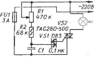
Figure 3. Dimmer using a composite dinistor
Such a circuit contains very few details: instead of two dinistors, as in the previous circuit, only one is used, but it is composite. It’s just that in one case two identical dinistors are switched in on-parallel, therefore, such a dinistor can work in an alternating current circuit, the polarity of the inclusion does not matter. It will work in any case, if, of course, serviceable.
By the way, these dinistors are used in energy saving lamps, therefore, if there is a need for such details, do not discard the immediately damaged lamp. There is also a small remark: dinistors are not "called" by the tester, so you should not immediately throw them away, you need to check in the circuit.
The power switch is made on a triac, the control electrode of which is connected directly to a bi-directional dinistor. As soon as the voltage across the capacitor C1 reaches the threshold of the dinistor, a control pulse will be formed on the UE of the triac, and then everything will be as described above.
Integrated power and dimmer controls
One of the typical representatives of such regulators is chip KR1182PM1A. Outwardly, it looks like a regular digital or analog microcircuitsince it is made in a standard DIP-16 package. This is such a plastic rectangle with 16 pins. Using just a few hinged parts, you can create some interesting practical designs: the smooth inclusion of light, twilight switch, just a power regulator.
As an integral part, the microcircuit easily fits into the composition of various power control devices. At the same time, it is capable of switching loads up to 150W without external power elements - triacs or thyristors. If you turn on two microcircuits in parallel, simply soldering them into two floors, then the load power can be doubled. The simplest circuit for switching on the microcircuit is shown in Figure 4.
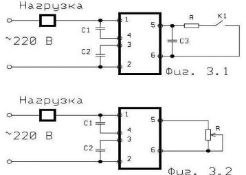
Figure 4. Dimmer on the KR1182PM1 chip
But this, it turns out, is not the easiest and most economical option.For the laziest, in the best sense of the word, there is integrated power controllersthat use only two hinged parts - the actual light bulb and a variable resistor, and the power of the resistor does not exceed one watt. Such are used as a volume control in old equipment. The connection diagram of such a “microcircuit” is shown in Figure 5, and the appearance in Figure 6.
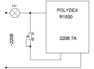
Figure 5. Connection diagram of the POLYDEX R1500 integrated power regulator
Figure 6 shows the appearance of the POLYDEX R1500 integrated power regulator.
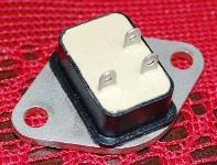
Figure 6. POLYDEX R1500. Appearance
Previous parts of the article:
Homemade dimmers. Part one. Types of Thyristors
Homemade dimmers. Part two. Thyristor device
Homemade dimmers. Part three. How to control a thyristor?
Homemade dimmers. Part Four Thyristor Practical Devices
Boris Aladyshkin
See also at bgv.electricianexp.com
:

