Categories: Microcontroller circuits
Number of views: 19709
Comments on the article: 0
Motor and servo control with Arduino
In simple designs of automation systems, it is often necessary not only to read the readings of sensors, but also to set in motion mechanisms. For this, a variety of electric motors are used. The simplest and most popular option is a DC motor. He won the love of lovers with his accessibility, ease of speed adjustment. If the task is to move any mechanism to a given angle or distance, it is convenient to use a servo drive or a stepper motor.
In this article, we look at servos and small DC motors, connecting them to an Arduino board, and adjusting the DCT.
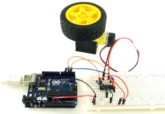
DC motor
The most common electric motor that is used in portable devices, toys, radio-controlled models and other devices. Permanent magnets are fixed to the stator on small electric motors, and a winding to the rotor.
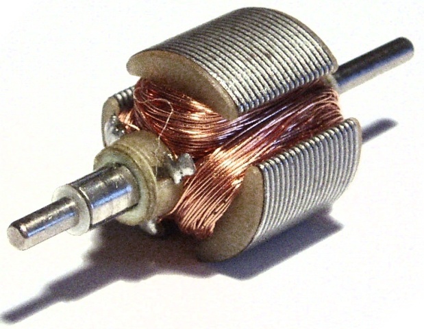
Current is supplied to the winding through the brush assembly. Brushes are made of graphite, sometimes copper sliding contacts are found. Brushes glide over lamellas located at one end of the rotor. If you do not go into details, then its rotation speed depends on the current of the armature winding.
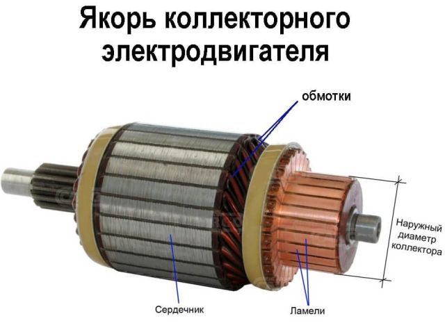
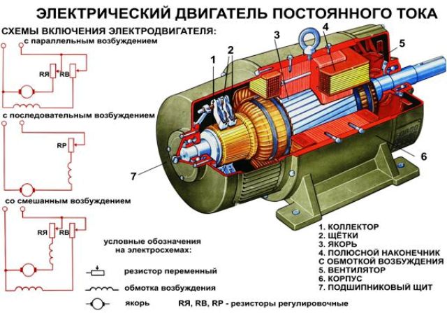
On large DC motors, on the stator, there is an excitation winding connected to the rotor winding (through the brush assembly) in a certain way (serial, parallel or mixed excitation). Thus, the desired torque and number of revolutions are achieved.
Speed control
When connected to the mains, the DC motor starts to rotate at rated speed. To reduce the speed you need to limit the current. To do this, ballast resistances are introduced, but this reduces the efficiency of the installation as a whole and an excess heat source appears. For more effective regulation of voltage and current, another method is used - PWM control.
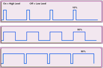
A method of controlling pulse-width modulated signal (voltage) is to generate the desired voltage value by changing the pulse width, with a constant duration of the period (frequency).
That is, the period is divided into two parts:
1. Impulse time.
2. Pause time.
The ratio of the pulse time to the total time of the period is called the duty cycle:
Ks = ti / tper
the reciprocal is called "duty cycle":
D = 1 / KZ = tper / t and
To describe the operating mode of the PWM controller, both concepts are used: both duty cycle and duty cycle.
The current consumption of the motor depends on its power. The number of revolutions, as was said, depends on the current. The current can be adjusted by changing the amount of voltage applied to the windings. In fact, when powered by a voltage that exceeds the nominal value according to the motor certificate, its speed will also exceed the nominal speed. However, such operating modes are dangerous for the motor, since a greater current flows in the windings, which causes their increased heating.
If damage to the engine from short-term impulses or repeatedly-short-term operating modes is minimal, then during prolonged operation at high voltage and revs it will burn out or its bearings will heat up and wedge, and then the windings will burn out if the power supply is not disconnected.
If the input voltage is too low, the small motor may simply not have enough power to move. Therefore, it is necessary to experimentally find out the normal speed and voltage for a particular engine not exceeding the nominal.
We connect to arduino
I had a small motor, it seems from a cassette player, which means that its rated voltage will be below 5 volts, then the output power of the arduino will be enough. I will power it from the “5V” pin, i.e. from the output of the linear stabilizer located on the board. According to the scheme that you see below.
I don’t know the current of this motor, so I connected it to the power, and I installed a field-effect transistor between the motor and the power pin, on the gate of which a signal from the PWM output was applied, any of the available ones can be used.
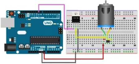
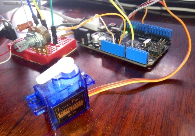
To adjust the speed, I added a variable resistor to the circuit, connecting it to the analog input A0. For a quick connection, I used a solderless breadboard, which is also called the breadboard.
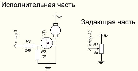
I installed a current-limiting resistor in the transistor wiring (to reduce the gate charge current, this will save the port from combustion and the microcontroller’s power supply from subsidence and its freezing) by 240 Ohms, and pulled it to the ground with a 12 kOhm resistor, this must be done to make it more stable the shutter tank worked and discharged faster.
Details on field effect transistors described in an article on our website. I used a powerful, common and not too expensive mosfet with an n-channel and built-in IRF840 reverse diode.
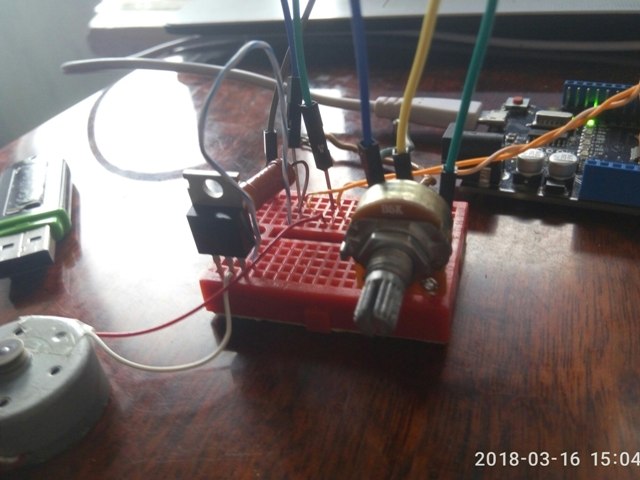
This is what my laboratory stand assembly looks like:
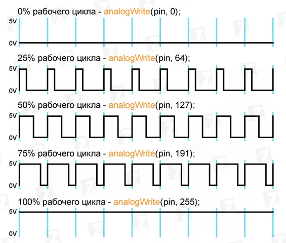
The PWM control function is called when writing to the corresponding output (3, 5, 6, 9, 10, 11) values from 0 to 255 with the AnalogWrite command (pin, value). The logic of her work is depicted in the graphs below.
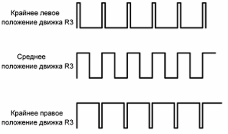
Such a signal is applied to the gate of the transistor:
The program code to the disgrace is short and simple, in detail all these functions have been described in previous articles about arduino.
int sensorPin = A0; // input from potentiometer
int motorPin = 3; // PWM output to the gate of the camera
void setup () {
pinMode (motorPin, OUTPUT);
}
void loop () {
analogWrite (motorPin, map (analogRead (sensorPin), 0, 1023, 0, 256));
}
In the analogWrite function, I assign a value to the PWM output, through the map command, its use allows you to remove several lines of code and one variable.
This is a working scheme and it is great for observing processes when adjusting the load power, the brightness of the LEDs, the engine speed, you just need to connect the desired load instead of the engine. At the same time, instead of 5V, any voltage can be applied to the load, for example 12V, do not forget to connect the minus power supply to the contact, for example 12V, do not forget to connect the minus power supply to the GND pin on the microcontroller board.
In arduino, the PWM frequency, when called through the analogWrite function, is only 400 Hz, at the minimum voltage values, a hum of the corresponding frequency was heard from the motor windings.
Servos
An engine that can be in a predetermined position, and when exposed to external factors, for example, a forced deflection of the shaft, keeps its position unchanged - is called a servo drive. In general, the definition sounds a little different:
Servo is a negative feedback driven motor.
Typically, three wires come out of a servo drive:
-
Plus power.
-
Less power.
-
Control signal.
The servo drive consists of:
-
DC motor (or brushless motor);
-
Management fees;
-
Position transmitter (encoder for servos with a rotation angle of 360 ° or a potentiometer for servos with a rotation angle of 180 °);
-
Reducing gear (lowers engine speed, and increases torque on the drive shaft).
The control unit compares the signal on the built-in position sensor and the signal that came through the control wire, if they differ, then there is a rotation at an angle at which the difference between the signal is leveled.

Main characteristics of servos:
-
Turning speed (time during which the shaft rotates through an angle of 60 °);
-
Torque (kg / cm, i.e. how many kilograms the engine can withstand on the lever 1 cm from the shaft);
-
Supply voltage;
-
Current consumption;
-
By the control method (analog or digital, there is no significant difference, but digital is faster and more stable).
Typically, the signal period is 20 ms, and the duration of the control pulse:
-
544 μs - corresponds to 0 °;
-
2400 μs - corresponds to an angle of 180 °.
In rare cases, the pulse length may differ, for example, 760 and 1520 μs, respectively, this information can be clarified in the technical documentation for the drive. One of the most popular hobby servos is the Tower Pro SG90 and similar models.It is inexpensive - about 4 dollars.
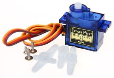
It holds 1.8 kg / cm on the shaft, and complete with it are mounting screws and levers with splines for the shaft. In fact, this baby is quite strong, and it is very problematic to stop it with one finger - the drive itself starts to drop out of the fingers - such is its strength.
Servo control and Arduino
As already mentioned, the control is carried out by changing the pulse duration, but do not confuse this method with PWM (PWM), its correct name is PDM (Pulse Duration Modulation). Slight deviations in the signal frequency (20 ms - duration, frequency 50 Hz) do not play a special role. But do not deviate from the frequency by more than 10 Hz, the engine can run jerkily or burn out.
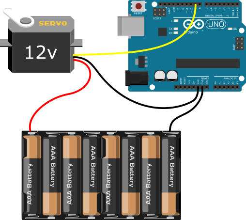
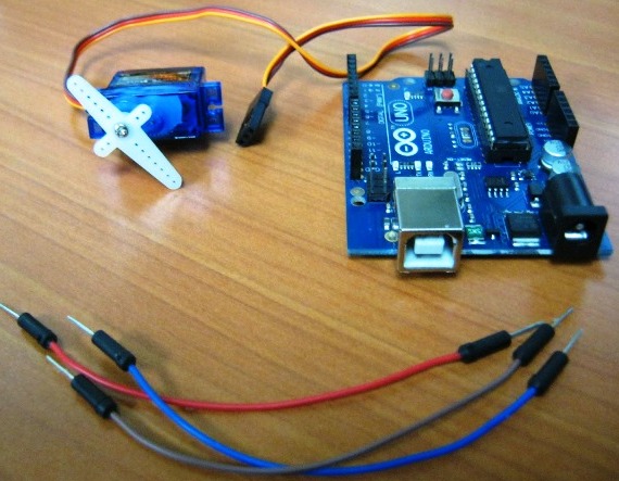
The connection to the arduino is quite simple, you can also power the drive from a 5v pin, but not desirable. The fact is that at the start there is a small jump in current, this can cause a power drawdown and False microcontroller outputs. Although 1 small drive (type SG90) is possible, but no more.
To control such servos with arduino, you have the Servo library built into the IDE, it has a small set of commands:
-
attach () - add a variable to the pin. Example: drive name.attach (9) - connect a servo to pin 9. If your drive needs non-standard lengths of control pulses (544 and 2400 μs), then they can be set separated by a comma after the pin number, for example: servo.attach (pin, min angle (μs), max angle in the ISS));
-
write () - sets the angle of rotation of the shaft in degrees;
-
writeMicroseconds () - sets the angle through the pulse length in microseconds;
-
read () - determines the current position of the shaft;
-
attached () - Checks if a pin is set with a servo connected;
-
detach () - cancel attach command.
This library allows you to control 12 servos from UNO, Nano and the like boards (mega368 and 168), while the ability to use PWM on pin 9 and 10 disappears. If you have MEGA, you can control the 48th servers, but the PWM on pins 11 and 12 will disappear, if you use up to 12 servos, then the PWM will remain fully functional on all contacts.
If you connected this library, you will not be able to work with 433 MHz receivers / transmitters. There is a Servo2 library for this, which is otherwise identical.

Here is an example of the code that I used for experiments with a servo drive, it is in the standard set of examples:
#include
Servo myservo; // declared variable name for myservo servo
int potpin = 0; // pin for connecting the setting potentiometer
int val; // variable to save the results of reading the signal from the potentiometer
void setup () {
myservo.attach (9); // set 9 pin as control output for servo
}
void loop () {
val = analogRead (potpin); // results of reading the potentiometer saved in trans. val, they will be in the range from 0 to 1023
val = map (val, 0, 1023, 0, 180); // translate the measurement range from analog input 0-1023
// in the range of tasks for servo 0-180 degrees
myservo.write (val); // pass the conversion signal from pot-ra to control servo input
delay (15); // delay is needed for stable operation of the system
Conclusion
Using the simplest electric motors paired with an arduino is a fairly simple task, while mastering this material expands your capabilities in the field of automation and robotics. The simplest robots or radio-controlled models of cars consist of such motors, and servos are used to control the rotation of the wheels.
In the examples considered, a potentiometer was used to set the angle of rotation or speed of rotation, any other signal source can be used instead, for example, rotation or change in speed may occur as a result of information received from sensors.
An example of the use of servos in alternative energy: tracking the angle of incidence of sunlight and adjusting the position of solar panels in power plants.
To implement such an algorithm, you can use several photoresistors or other optoelectronic devices for measuring the amount of incident light and, depending on their readings, set the angle of rotation of the solar panel.
See also at i.electricianexp.com
:
