Categories: Microcontroller circuits
Number of views: 16,299
Comments on the article: 0
How to connect incremental encoder to Arduino
Often in devices on microcontrollers you need to organize the management of menu items or implement some adjustments. There are many ways: use buttons, variable resistors, or encoders. The incremental encoder allows you to control something by means of the endless rotation of the handle. In this article, we will look at how to make the incremental encoder and Arduino work.
Incremental Encoder Features
The incremental encoder, like any other type of encoder, is a device with a rotating handle. Distantly, it resembles a potentiometer. The main difference from the potentiometer is that the encoder handle rotates 360 degrees. He has no extreme provisions.
Encoders come in many types. Incremental differs in that with its help it is impossible to know the position of the handle, but only the fact of rotation in some direction - to the left or to the right. By the number of signal pulses, you can already calculate at what angle it turned.
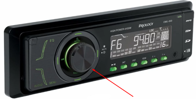
That way you can pass microcontroller command, manage the menu, volume level, for example, and so on. In everyday life, you could see them in car radios and other equipment. It is used as a multifunctional level adjustment organ, equalizer and menu navigation.
Principle of operation
Inside the incremental encoder there is a disk with labels and sliders that come into contact with them. Its structure is similar to a potentiometer.
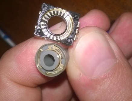
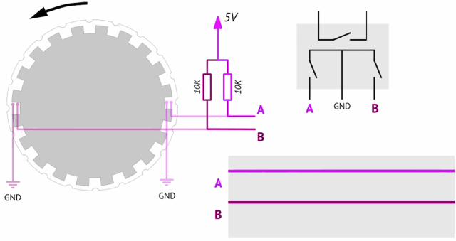
In the figure above you see a disk with marks, they are needed to interrupt the electrical connection with the movable contact, as a result you get data about the direction of rotation. The design of the product is not so important, let's understand the principle of operation.
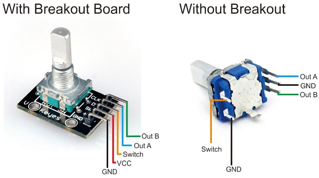
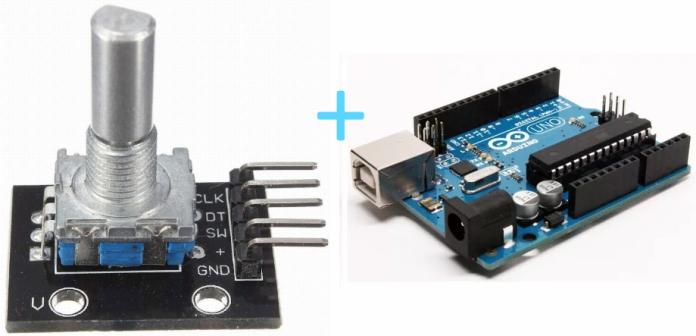
The encoder has three information outputs, one common, the other two are usually called “A” and “B”, in the figure above you see the encoder pin with a button - you can receive a signal when you click on its shaft.
What signal will we receive? Depending on the direction of rotation, the logical unit will first appear on pin A or B, so we get a phase-shifted signal, and this shift allows us to determine which direction. The signal is obtained in the form of a rectangular shape, and the microcontroller is controlled after processing the data of the direction of rotation and the number of pulses.

The figure shows the symbol of the disk with the contacts, in the middle there is a graph of the output signals, and on the right is the status table. This device is often drawn as two keys, which is logical, because in fact we get a signal “forward” or “back”, “up” or “down”, and the number of actions.
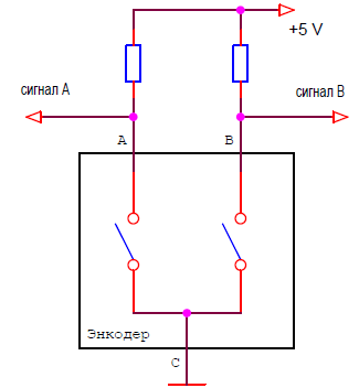
Here is an example of a real encoder pinout:
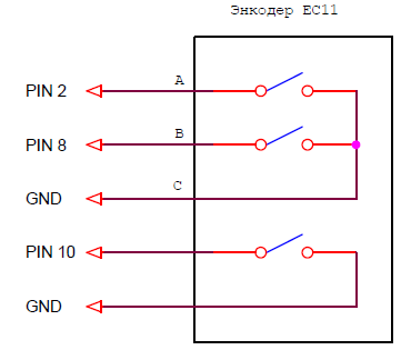
Interesting:
A faulty encoder can be replaced with two buttons without locking, and vice versa: homemade control in which two of these buttons can be finalized by setting the encoder.
In the video below, you see the alternation of the signal at the terminals - during smooth rotation, the LEDs light up in the sequence reflected in the previous graph.
No less clearly illustrated in the following animation (click on the picture):
The encoder can be both optical (the signal is generated by emitters by photodetectors, see the figure below), and magnetic (it works on the Hall effect). In this case, he has no contacts and longer service life.
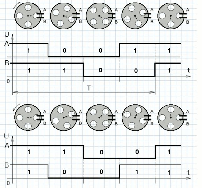
As already mentioned, the direction of rotation can be determined by which of the output signals has previously changed, but this is how it looks in practice!
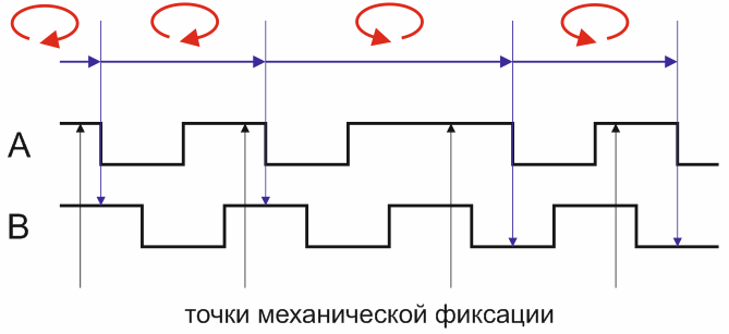
The control accuracy depends on the resolution of the encoder - the number of pulses per revolution. The number of pulses can be from units to thousands of pieces. Since the encoder can act as a position sensor, the more pulses, the more accurately the determination will occur.This parameter is referred to as PPR - pulse per revolution.
But there is a small nuance, namely, a similar designation LPR is the number of labels on the disk.
And the number of processed pulses. Each label on the disk gives 1 rectangular pulse on each of the two outputs. The impulse has two fronts - the rear and the front. Since there are two ways out, we get 4 pulses in total from each of them, the values of which you can process.
PPR = LPRx4
Connect to Arduino
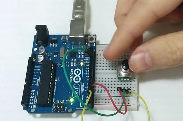
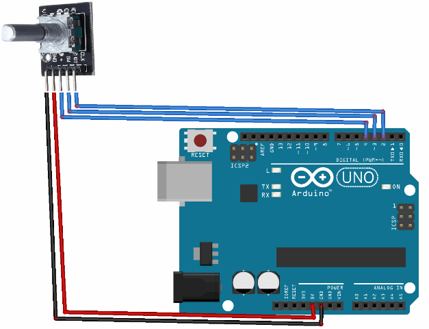
We figured out what you need to know about the incremental encoder, now let's find out how to connect it to the Arduino. Consider the connection diagram:
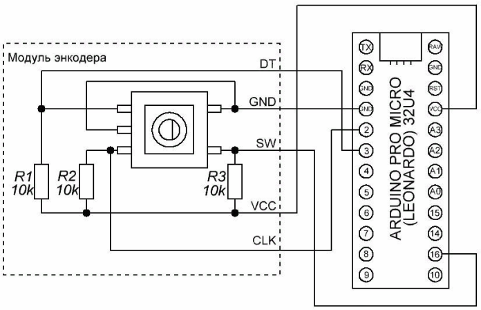
An encoder module is the board on which the incremental encoder and pull-up resistors are located. You can use any pins.
If you do not have a module, but a separate encoder, you just need to add these resistors, the circuit will not differ in principle. To check the direction of rotation and its operability in conjunction with Arduino we can read information from the serial port.
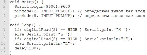
Let's analyze the code in more detail, in order. In void setup (), we announced that we would use communication through the serial port, and then set pins 2 and 8 in the input mode. Select pin numbers yourself based on your connection scheme. The INPUT_PULLUP constant sets the input mode, the arduino has two options:
-
INPUT - input without pull-up resistors;
-
INPUT_PULLUP - connection to the input of pull-up resistors. There are already resistors inside the microcontroller through which the input is connected to the power plus (pullup).
If you use resistors to tighten to the power plus as shown in the diagrams above or use the encoder module - use the INPUT command, and if for some reason you cannot or do not want to use external resistors - INPUT_PULLUP.
The logic of the main program is as follows: if we have one at the input “2”, it outputs port H to the monitor, if not, L. Thus, when you rotate one way on the serial port monitor, you get something like this: LL HL HH LH LL. And vice versa: LL LH HH HL LL.
If you carefully read the lines, you probably noticed that in one case the first character acquired a value, and in the other case, the second character first changed.
Conclusion
Incremental encoders have found wide practical application in amplifiers for acoustic systems - they were used as a volume control, in car radios - to adjust sound parameters and navigate menus, in computer mice with it you scroll pages daily (a wheel is installed on its shaft) . And also in measuring tools, CNC machines, robots, selsyn not only as controls, but also measuring values and determining the position.
See also at i.electricianexp.com
:

