Categories: How does it work
Number of views: 3979
Comments on the article: 0
How the servo is arranged and works
Low-current servos driven by arduino (micro servo motor) are widely used today in amateur robotics, they make small desktop machines and many other things interesting and useful in the household. Even just at the hobby level, such servos find a ton of diverse uses. Let's see what a servo is in its simplest form, how it is fundamentally designed and how it works.
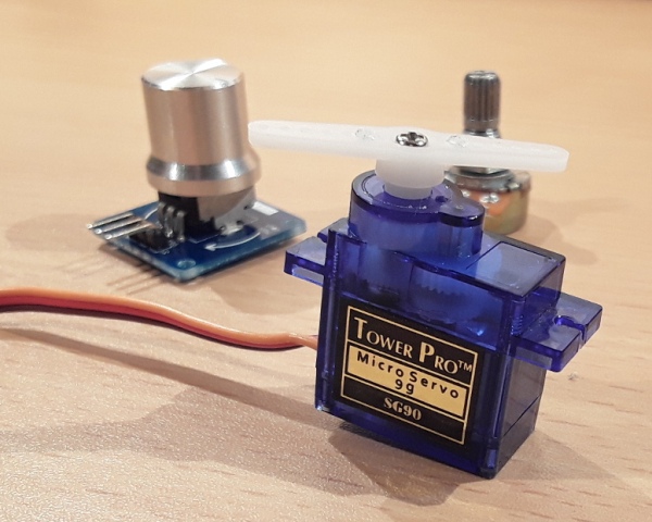
The word “servo drive” itself can be translated as “servo drive”. That is, it is such a driving device that contains an engine controlled by negative feedback, which allows precise movements with verified positioning of the working body.
In principle, a servo drive can be called an electric motor, in the control system of which there is a position sensor of the working device (or just a shaft), the current parameters from which determine how, where and how much the motor rotor should or should not turn to obtain the desired result. Typically, in such a system, there is a drive control unit that analyzes the parameters from the sensor and, in accordance with them, controls the motor power.
Thus, although the servo drive works automatically, the positioning process of the working body is very accurate due to the correct processing of the signal from the sensor by the control board. For example, the control goal may simply be to maintain a specific value for a particular parameter of said sensor. So it becomes clear why the drive is called tracking - it monitors the state of the sensor.
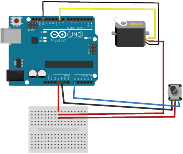
An engine with an installed gearbox can have only three or four wires coming from it. Two wires supply power to the engine, from the third - the signal from the sensor is removed, the fourth can be designed to power the sensor.
Usually the power wires are red and black or red and brown - these are the plus and minus (ground) power wires. White or yellow - a signal wire from the sensor, through this wire a feedback signal about the current state of the system comes to the control board.
A simple servo with gearbox (servo) and potentiometer is a great example to understand how the feedback works in the servo control system.
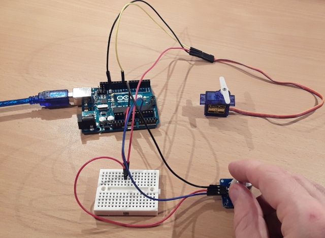
The potentiometer has three outputs. On those conclusions that on the sides - power is supplied, and the average in fact - output with resistive voltage divider. If you change the position of the handle of the potentiometer, then the magnitude of the voltage between the supply minus and its average output will change in proportion to the change in resistance between the minus and the average output.
Suppose, in the leftmost position, the voltage at the middle output of the potentiometer will be minimum, and in the rightmost position, it will be maximum. It turns out that the voltage at the middle terminal of the potentiometer is determined by the position of its handle, that is, by what angle it is turned from the initial position, in which the voltage at the middle terminal is minimal. Typically, potentiometers with a nominal resistance of 5-10 kΩ are used.
And how does the servo work here? The potentiometer handle in this servo drive is connected to the motor shaft through a gearbox. This means that when the engine is running and its rotor rotates, the handle of the potentiometer rotates and therefore the resistance at its average output changes.
In the extreme left position, for example, on the middle terminal there will be 0 volts, in the middle position - 2.5 volts, and in the extreme right - 5 volts. To simplify, we assume that the knob of the potentiometer is capable of rotating around its axis by 180 degrees, which means 2.5 volts on the average output will correspond to a turn of the knob 90 degrees.
If the control board receives information that the average output is 5 volts, and it is necessary to create a turn up to 90 degrees, then a certain polarity power will automatically be applied to the motor until it rotates the gearbox output (and, in place with it, the potentiometer knob) from right to left, the potentiometer will not bring to the desired position. As soon as 2.5 volts becomes on the middle output of the potentiometer, the motor will stop receiving power from the control board.
In a similar way, a turn in the opposite direction will be realized: if the average output is 0 volts, then the polarity of the motor supply will be such that the potentiometer knob will turn through the gearbox from left to right, until the voltage reaches 2.5 volts, corresponding to a turn of the knob 90 degrees. This is a rather crude example, but it is quite clear.
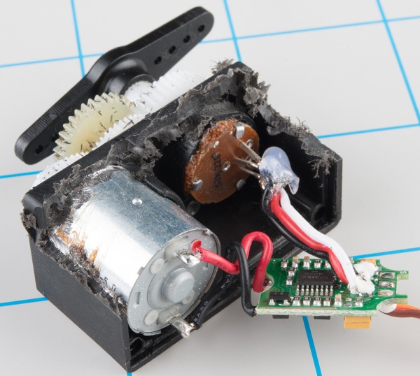
The gearbox is necessary here in order to convert the high revolutions of the low-power motor shaft to low revolutions with great effort, which will allow, firstly, to turn the potentiometer, and secondly, to do it slowly and accurately. The gearbox consists of gears, on the motor shaft there is a small one that rotates a large one, in the center of which a small one, etc.
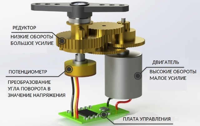
Servos are characterized by several main parameters. The first main parameter is the force on the shaft (torque divided by the acceleration of gravity), which is measured in small models in kg / cm and is determined at the rated supply voltage of the motor. For example, a torque of 10 kg / cm means that when the distance to the axis of the output shaft is 1 cm, a load of 10 kg can be held on it.
The second important parameter is the turning speed, which is indicated in sec / 60 degrees. This parameter shows how long it takes for the servo drive to rotate its output shaft 60 degrees. For example, 0.2sec / 60 degrees. Next come such parameters as the supply voltage, rotation angle (180 or 360 degrees) and the type of gearbox (gear material).
Features connecting devices to Arduino
See also at bgv.electricianexp.com
:
