Categories: Electric motors and their application, Microcontroller circuits
Number of views: 24464
Comments on the article: 0
Arduino and stepper motor: fundamentals, schemes, connection and control
Stepper motors are used to control the position of something, or to rotate the working unit at a given speed and angle. Such features made it possible to use it in robotics, numerically controlled machines (CNC), and other automation systems. In this article, we will consider a number of issues related to the construction of stepper motors and how to control them using the Arduino microcontroller.
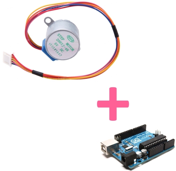
Stepper motor differs from the usual
All electric motors used in practice operate due to electrodynamic phenomena and processes occurring in the magnetic fields of rotors and stators. As we have already mentioned, any engine consists of at least two parts - mobile (rotor) and motionless (stator). For its rotation, it is necessary that the magnetic field also rotates. The rotor field rotates after the stator field.
In principle, such basic information is sufficient to understand the general picture of the operation of electric motors. However, in fact, industry produces various motor options, among which:
1. Squirrel-cage or wound rotor induction motor.
2. Synchronous motor with field windings or with permanent magnets.
3. DC motor.
4. Universal collector motor (it works on both direct current and alternating current, because the rotor windings themselves are connected and disconnected from the contacts of the power source due to the design of lamellas and anchors).
5. Brushless DC motors (BLDC).
6. Servos.
7. Stepper motors.
The last two species are of particular value, due to the possibility of their, to a certain extent, accurate positioning in space. Let's take a closer look at the design of the stepper motor.
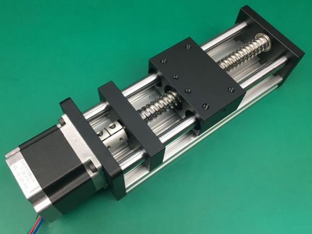
Definition
A stepper motor is called a brushless synchronous motor. A certain number of windings are located on the stator, the connection of which causes the rotor to rotate a certain angle, depending on the number of steps. In other words, the current in the stator winding causes the shaft to rotate at a discrete angle.
With a uniform and sequential change in the polarity of the voltage across the windings and the switching of the energized windings, the stepper motor rotates, similar to a conventional electric motor, although in fact a regular rotation at a fixed angle simply takes place.
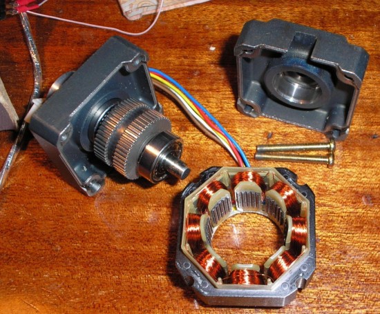
The stepper motor is sometimes called the motor. with a finite number of rotor positions. It doesn’t sound very clear, let's figure it out. Imagine a conventional engine - the position of its rotor is not fixed in any way, that is, it simply rotates while the power is connected, and when it turns off, it stops after some time, depending on its inertia. The positions of the rotor can be as many as you like, but they can differ by the smallest fractions of a degree.
In a stepper motor, connecting a winding or several windings causes a “magnetization” of the rotor with respect to these windings. Outwardly, it looks exactly like turning the shaft at a certain angle (pitch). Since the number of steps is one of the important characteristics of this type of electric drive, the number of rotor positions is equal to the number of steps. It is difficult for beginners to understand how this can be, and how it rotates in this case - in fact, everything is quite simple, we will show this in the illustrations and descriptions below.
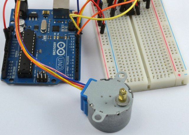
Design
Excitation windings are fixed on the stator of the electric motor. Its rotor is made of soft magnetic or hard magnetic materials. The material of the rotor depends on the torque and fixation of the shaft with de-energized windings. These parameters can be critical.
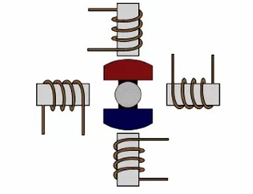
Therefore, magnetically solid rotors (they are also with permanent magnets) and magnetically soft (reactive) rotors are distinguished, in addition to them there are hybrid rotors.
The hybrid rotor is made toothed, the number of teeth corresponds to the number of steps. The teeth are located along the axis of the rotor. Moreover, such a rotor is divided into two parts across. A permanent magnet is installed between them, so each of the halves of the rotor is a magnet pole. It should also be said that half of the rotor is rotated half the pitch of the teeth relative to each other.
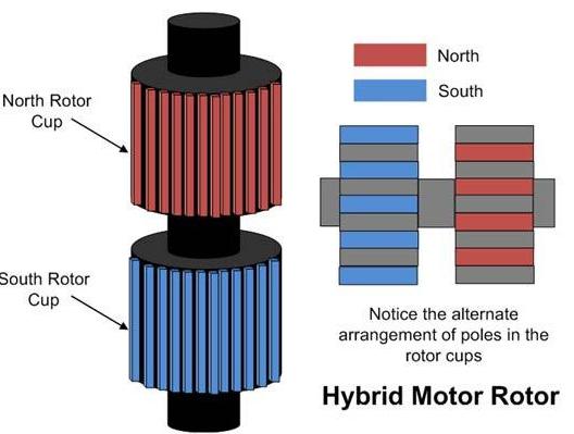
As already mentioned, such an engine is synchronous, and the process of its rotation consists in creating a rotating field of the rotor, which the magnetic rotor seeks, and this is realized by switching the windings by the controller in turn.
Types of stepper motors for the design of windings are divided into three main groups according to the connection scheme of the windings:
1. Bipolar.
2. Unipolar.
3. With four windings.

Most bipolar electric motors have 4 contacts - these are conclusions from two windings. Inside the engine, they are by and large not connected to each other. The main problem is that it is necessary to ensure the switching of power polarity, which means that the driver and the control process itself will become more complicated.
Unipolar resemble the connection of the windings according to the pattern of the star. In other words, you have 5 conclusions - 4 of them are the ends of the windings, and 1 is the connection point of all the windings.
To control such an engine, you just need to alternately supply power to each end of the winding (or a couple of them, depending on the selected rotation mode), this way half the winding will be powered every time. It can work in bipolar mode, if you feed the entire winding completely bypassing the tap from its middle.
Motors with 4 windings have the advantage that you can connect the windings in any way convenient for you and get both a bipolar and a unipolar motor.
Control modes
There are 4 main stepper motor control modes:
1. Wave control.
2. Full step.
3. Half-step.
4. Microstepping
Volnov control is called control of one winding. Those. at the same time, current flows through one of the windings, hence two distinctive features - low power consumption (this is good) and low torque (this is bad).
In this case, this engine takes 4 steps in one revolution. Real motors take dozens of steps in one revolution, this is achieved by a large number of alternations of magnetic poles.
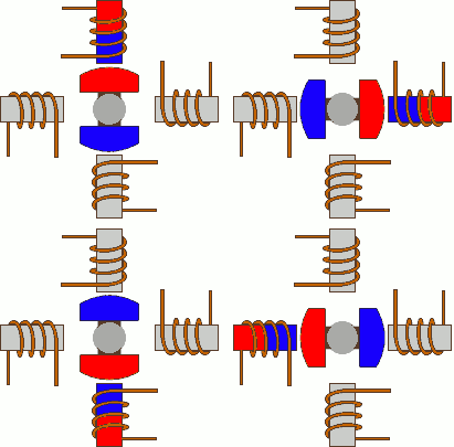
Full Step Management is the most commonly used. Here, the voltage is supplied not to one winding, but to two at once. If the windings are connected in parallel, then the current doubles, and if in series, the supply voltage doubles, respectively. On the one hand, in this control method, the engine consumes more energy, on the other hand, 100% torque, unlike the previous one.
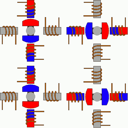
Half-step control It is interesting in that it becomes possible to more accurately position the motor shaft, due to the fact that halves are added to whole steps, this is achieved by combining the previous two operating modes, and the windings alternate, then turning on in pairs, then one at a time.
It is worth considering that the moment on the shaft floats from 50 to 100%, depending on whether 1 or 2 two windings are involved at the moment.
Even more accurate is microstepping. It is similar to the previous one, but differs in that the power to the windings is not supplied to the full extent, but gradually changing. Thus, the degree of impact on the rotor of each of the windings changes and the angle of rotation of the shaft in intermediate steps varies smoothly.
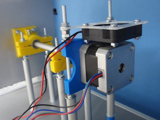
Where to get a stepper motor
You will always have time to buy a stepper motor, but real radio amateurs, home-made people and electronic engineers are famous for the fact that they can do something useful out of garbage. Surely you have at least one stepper motor in your home. Let's figure out where to look in order to find such an engine.
1. The printer.Stepper motors can stand on the rotation of the paper feed shaft (but there may also be a DC motor with a displacement sensor).
2. Scanners and MFPs. Scanners often install a stepper motor and a mechanical part along which the carriage guides, these parts can also be useful in developing a home-made CNC machine.
3. CD and DVD drives. You can also get rods and screw shafts for homemade products and various CNCs in them.
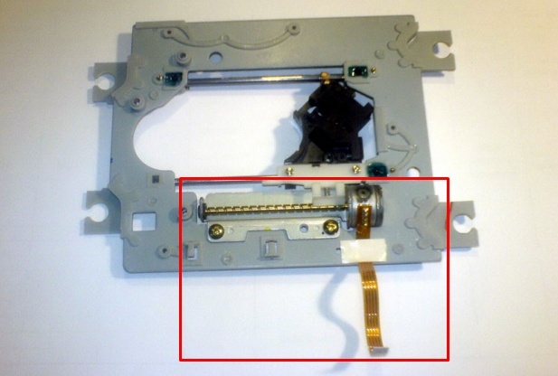
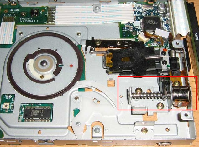
4. Floppy drives. The floppy disks also have stepper motors, especially floppy files of the 5.25 ”format.
Stepper motor driver
To control the stepper motors use specialized driver microcircuits. Mostly this is an H-bridge of transistors. Thanks to this inclusion, it becomes possible to turn on the voltage of the desired polarity to the winding. These chips are also suitable for controlling DC motors with support for changing the direction of rotation.
In principle, very small engines can be started directly from the pins of the microcontroller, but usually they give up to 20-40 mA, which in most cases is not enough. Therefore, here are some examples of drivers for stepper motors:
1. Boards based on L293D. There are a lot of them, one of them is sold under the domestic brand Amperka under the name Troyka Stepper, an example of its use in a real project is shown in the video below. The advantage of this particular board is that it has logic chips that can reduce the number of pins used to control it.
The chip itself operates under a voltage of 4.5-36V and produces a current of up to 600mA-1A, depending on the IC case.
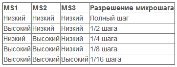
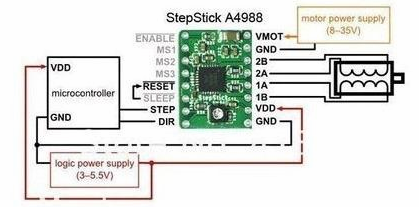
2. A4988 based driver. It is powered by voltage up to 35V, can withstand current up to 1A without a radiator, and with a radiator up to 2A. It can control the engine, both in whole steps and in parts - from 1/16 of a step to 1 step, only 5 options. Contains two H-bridges. Using the tuning resistor (seen in the right photo), you can set the output current.
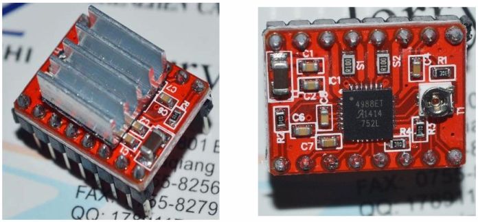
The step size is set by the signals at the inputs MS1, MS2, MS3.
Here is a diagram of its connection, each pulse at the STEP input sets the engine to rotate 1 step or a microstep.
3. The driver based on ULN2003 works with 5 and 12 V motors and produces a current of up to 500 mA. On most boards, there are 4 LEDs indicating the operation of each channel.
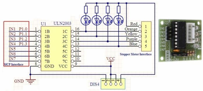
Also on the board you can see the terminal block for connecting motors, by the way, many of them are sold with this connector. An example of such an engine is a 5V model - 28BYJ-48.
And these are not all driver options for stepper motors, in fact there are even more of them.
Connection to Arduino driver and stepper motor
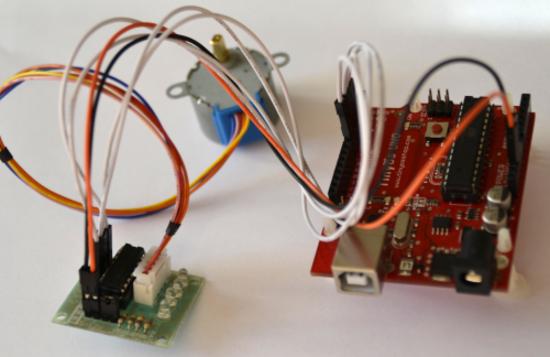
In most cases, you need to use a microcontroller paired with a driver for a stepper motor. Let's look at the connection diagram and code examples. Consider a connection based on the latest driver listed - ULN2003 to the Arduino board. And so it has 4 inputs, they are signed as IN1, IN2, etc. They need to be connected to the digital pins of the Arduino board, and a motor should be connected to the driver as shown in the figure below.
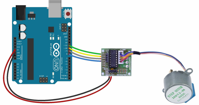
Further, depending on the control method, you must apply to the inputs 1 or 0 from these pins including 1 or 2 windings in the required sequence. The code for the full-step control program looks something like this:
int in1 = 2;
int in2 = 3;
int in3 = 4;
int in4 = 5;
const int dl = 5;
void setup () {
pinMode (in1, OUTPUT);
pinMode (in2, OUTPUT);
pinMode (in3, OUTPUT);
pinMode (in4, OUTPUT);
}
void loop () {
digitalWrite (in1, HIGH);
digitalWrite (in2, HIGH);
  digitalWrite (in3, LOW);
  digitalWrite (in4, LOW);
  delay (dl);
  digitalWrite (in1, LOW);
  digitalWrite (in2, HIGH);
  digitalWrite (in3, HIGH);
  digitalWrite (in4, LOW);
  delay (dl);
  digitalWrite (in1, LOW);
  digitalWrite (in2, LOW);
  digitalWrite (in3, HIGH);
  digitalWrite (in4, HIGH);
  delay (dl);
  digitalWrite (in1, HIGH);
  digitalWrite (in2, LOW);
  digitalWrite (in3, LOW);
  digitalWrite (in4, HIGH);
  delay (dl);
}
It includes windings in the following sequence:

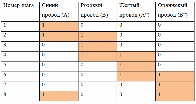
Here is the code for the half-step mode, as you can see, it is much more voluminous, since it involves a greater number of switching windings.
int in1 = 2;
int in2 = 3;
int in3 = 4;
int in4 = 5;
const int dl = 5;
void setup () {
pinMode (in1, OUTPUT);
pinMode (in2, OUTPUT);
pinMode (in3, OUTPUT);
pinMode (in4, OUTPUT);
}
void loop () {
digitalWrite (in1, HIGH);
digitalWrite (in2, LOW);
digitalWrite (in3, LOW);
  digitalWrite (in4, LOW);
  delay (dl);
  digitalWrite (in1, HIGH);
  digitalWrite (in2, HIGH);
  digitalWrite (in3, LOW);
  digitalWrite (in4, LOW);
  delay (dl);
  digitalWrite (in1, LOW);
  digitalWrite (in2, HIGH);
  digitalWrite (in3, LOW);
  digitalWrite (in4, LOW);
  delay (dl);
  digitalWrite (in1, LOW);
  digitalWrite (in2, HIGH);
  digitalWrite (in3, HIGH);
  digitalWrite (in4, LOW);
  delay (dl);
  digitalWrite (in1, LOW);
  digitalWrite (in2, LOW);
  digitalWrite (in3, HIGH);
  digitalWrite (in4, LOW);
  delay (dl);
  digitalWrite (in1, LOW);
  digitalWrite (in2, LOW);
  digitalWrite (in3, HIGH);
  digitalWrite (in4, HIGH);
  delay (dl);
  digitalWrite (in1, LOW);
  digitalWrite (in2, LOW);
  digitalWrite (in3, LOW);
  digitalWrite (in4, HIGH);
  delay (dl);
  digitalWrite (in1, HIGH);
  digitalWrite (in2, LOW);
  digitalWrite (in3, LOW);
  digitalWrite (in4, HIGH);
  delay (dl);
}
This program includes windings as follows:
To consolidate the information received, watch the useful video:
Conclusion
Stepper Motors Are Popular Among Arduins along with servos, because they allow you to create robots and CNC machines. The latter is helped by the abundance in the secondary market of super-cheap used optical drive drives.
See also at i.electricianexp.com
:
