Categories: Featured Articles » Practical Electronics
Number of views: 101678
Comments on the article: 0
What is a PWM controller, how is it arranged and works, types and schemes
Previously, a circuit with a step-down (or step-up, or multi-winding) transformer, a diode bridge, and a filter for smoothing ripples was used to power devices. For stabilization, linear circuits using parametric or integrated stabilizers were used. The main drawback was the low efficiency and high weight and dimensions of powerful power supplies.
All modern household electrical appliances use switching power supplies (UPS, UPS - the same thing). Most of these power supplies use a PWM controller as the main control element. In this article we will consider its structure and purpose.
Definition and main advantages
A PWM controller is a device that contains a number of circuitry solutions for managing power keys. In this case, control is based on information obtained through feedback circuits for current or voltage - this is necessary to stabilize the output parameters.
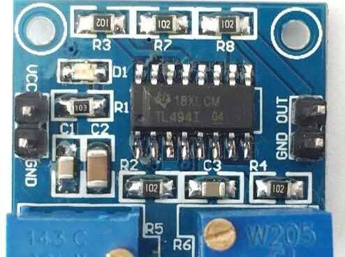
Sometimes, PWM controllers are called PWM pulse generators, but there is no way to connect feedback circuits, and they are more suitable for voltage regulators than to ensure a stable power supply to devices. However, in literature and Internet portals you can often find names like “PWM controller, on NE555” or “... on arduino” - this is not entirely true for the above reasons, they can only be used to control the output parameters, but not to stabilize them.
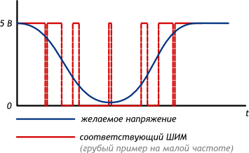
The abbreviation "PWM" stands for pulse-width modulation is one of the methods of modulating the signal not due to the magnitude of the output voltage, but rather due to a change in the width of the pulses. As a result, a simulated signal is formed due to the integration of pulses using C- or LC-chains, in other words - due to smoothing.
Conclusion: PWM controller - a device that controls the PWM signal.
Main characteristics
For a PWM signal, two main characteristics can be distinguished:
1. Pulse frequency - the operating frequency of the converter depends on this. Typical are frequencies above 20 kHz, in fact 40-100 kHz.
2. Duty cycle and duty cycle. These are two adjacent quantities characterizing the same thing. The fill factor can be denoted by the letter S, and the duty cycle D.
S = 1 / T,
where T is the signal period,
T = 1 / f
D = T / 1 = 1 / S
Important:
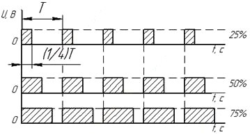
Fill factor - part of the time from the period when a control signal is generated at the controller’s output, always less than 1. The duty cycle is always greater than 1. At a frequency of 100 kHz, the signal period is 10 μs and the key is open for 2.5 μs, then the duty cycle is 0.25, in percent - 25%, and the duty cycle is 4.
It is also important to consider the internal design and purpose of the number of keys managed.
Differences from linear loss schemes
As already mentioned, an advantage over linear circuits for switching power supplies is a high efficiency (more than 80, and currently 90%). This is due to the following:
Suppose the smoothed voltage after the diode bridge is 15V, the load current is 1A. You need to get a stabilized 12V power supply. In fact, a linear stabilizer is a resistance that changes its value depending on the magnitude of the input voltage to obtain the nominal output voltage - with small deviations (fractions of volts) with changes in the input voltage (units and tens of volts).
On resistors, as you know, when electric current flows through them, thermal energy is released. On linear stabilizers, the same process occurs. The allocated power will be equal to:
Loss = (Uin-Uout) * I
Since in the example considered, the load current is 1A, the input voltage is 15V, and the output voltage is 12V, then we calculate the losses and efficiency of the linear stabilizer (Krenka or type L7812):
Loss = (15V-12V) * 1A = 3V * 1A = 3W
Then the efficiency is:
n = P useful / P loss
n = ((12V * 1A) / (15V * 1A)) * 100% = (12V / 15W) * 100% = 80%
If the input voltage rises to 20V, for example, then the efficiency will decrease:
n = 12/20 * 100 = 60%
Etc.
The main feature of PWM is that the power element, even if it is a MOSFET, is either fully open or completely closed and no current flows through it. Therefore, the loss of efficiency is due only to the loss of conductivity
(P = I2 * Rdson)
And loss switching. This is a topic for a separate article, so we will not dwell on this issue. Also, power supply losses occur in rectifier diodes (input and output, if the power supply is mains), as well as on conductors, passive filter elements and more.
General structure
Consider the general structure of an abstract PWM controller. I used the word "abstract" because, in general, they are all similar, but their functionality can still vary within certain limits, accordingly, the structure and conclusions will differ.
Inside the PWM controller, as in any other IC, there is a semiconductor chip on which a complex circuit is located. The controller includes the following functional units:
1. The pulse generator.
2. The source of the reference voltage. (AND HE)
3. Circuits for processing a feedback signal (OS): error amplifier, comparator.
4. The pulse generator controls integrated transistorsdesigned to control a power key or keys.
The number of power keys that a PWM controller can control depends on its purpose. The simplest flyback converters in their circuit contain 1 power switch, half-bridge circuits (push-pull) - 2 switches, bridge - 4.
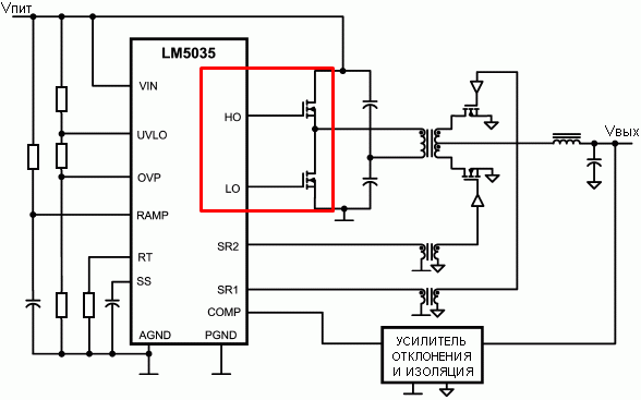
The key type also determines the choice of the PWM controller. To control a bipolar transistor, the main requirement is that the control current output of the PWM controller is not lower than the current of the transistor divided by H21e, so that it can be turned on and off simply by applying pulses to the base. In this case, most controllers will do.
In case of management insulated shutter keys (MOSFET, IGBT) there are certain nuances. For quick shutdown you need to discharge the shutter capacity. To do this, the gate output circuit is made of two keys - one of them is connected to the power source with an IC output and controls the gate (turns on the transistor), and the second is installed between the output and ground, when you need to turn off the power transistor - the first key closes, the second opens, closing shutter to the ground and discharges it.
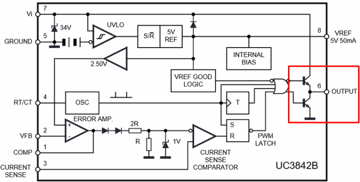
Interesting:
In some PWM controllers for low-power power supplies (up to 50 W), power switches are not used internally and externally. Example - 5l0830R
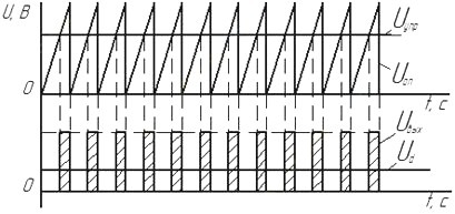
Generally speaking, the PWM controller can be represented as a comparator, on one input of which a signal from a feedback circuit (OS) is supplied, and a sawtooth-shaped changing signal is applied to the second input. When the sawtooth signal reaches and exceeds the OS signal in magnitude, an impulse arises at the output of the comparator.
When the signals at the inputs change, the pulse width changes. Let's say that you connected a powerful consumer to the power supply, and the voltage dipped at its output, then the OS voltage will also drop. Then in most of the period an excess of the sawtooth signal over the OS signal will be observed, and the pulse width will increase. All of the above is to some extent reflected in the graphs.
The operating frequency of the generator is set using the frequency-setting RC circuit.
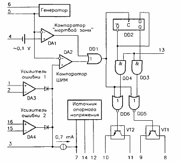
Functional diagram of a PWM controller using the TL494 as an example, we will examine it later in more detail. The pin assignment and individual nodes are described in the following subheading.
Pin assignment
PWM controllers are available in various packages. They can have conclusions from three to 16 or more. Accordingly, the flexibility of using the controller depends on the number of conclusions, or rather their purpose.For example, in a popular chip UC3843 - most often 8 conclusions, and in an even more iconic one - TL494 - 16 or 24.
Therefore, we consider the typical names of the conclusions and their purpose:
-
GND - the general conclusion is connected to the minus of the circuit or to the ground.
-
Uc (Vc) - microcircuit power.
-
Ucc (Vss, Vcc) - Output for power control. If the power sags, then it is likely that the power keys will not fully open, and because of this they will start to heat up and burn out. The conclusion is needed to disable the controller in a similar situation.
-
OUT - as the name implies, this is the controller output. The PWM control signal for the power switches is displayed here. We mentioned above that converters of different topologies have different numbers of keys. The name of the output may differ depending on this. For example, in controllers for half-bridge circuits, it may be called HO and LO for the upper and lower keys, respectively. At the same time, the output can be single-cycle and push-pull (with one key and two) - for controlling field-effect transistors (see explanation above). But the controller itself can be for single-cycle and push-pull circuits - with one and two output terminals, respectively. It is important.
-
Vref - voltage reference, usually connected to the ground through a small capacitor (microfarad units).
-
ILIM - signal from the current sensor. Needed to limit the output current. Connects to feedback circuits.
-
ILIMREF - it sets the trigger voltage of the ILIM leg
-
SS - a signal is generated for the soft start of the controller. Designed for a smooth exit to nominal mode. A capacitor is installed between it and the common wire to ensure a smooth start.
-
Rtct - conclusions for connecting a timing RC circuit, which determines the frequency of the PWM signal.
-
CLOCK - clock pulses for synchronizing several PWM controllers with each other, then the RC circuit is connected only to the master controller, and RT slaves with Vref, CT slaves are connected to the common one.
-
RAMP Is a comparison input. A sawtooth voltage is applied to it, for example, from the output of Ct. When it exceeds the value of the voltage at the output of the error amplification, a disconnecting pulse appears on the OUT - the basis for PWM control.
-
INV and NONINV - This is the inverting and non-inverting inputs of the comparator on which the error amplifier is built. In simple words: the higher the voltage on the INV, the longer the output pulses and vice versa. The signal from the voltage divider in the feedback circuit from the output is connected to it. Then the non-inverting input NONINV is connected to a common wire - GND.
-
EAOUT or Error Amplifier Output Russian Error amplifier output. Despite the fact that there are inputs of the error amplifier and with their help, in principle, you can adjust the output parameters, but the controller responds rather slowly to this. As a result of a slow reaction, circuit excitation can occur and it will fail. Therefore, signals from this pin are output to INV via frequency-dependent circuits. This is also called frequency correction of the error amplifier.
Examples of real devices
To consolidate the information, let's look at a few examples of typical PWM controllers and their switching schemes. We will do this using two microchips as an example:
-
TL494 (its analogues: KA7500B, КР1114ЕУ4, Sharp IR3M02, UA494, Fujitsu MB3759);
-
UC3843.
They are actively used. in power supplies for computers. By the way, these power supplies have considerable power (100 W and more on the 12V bus). Often used as a donor for conversion to a laboratory power supply or a universal powerful charger, for example for car batteries.
TL494 - Overview
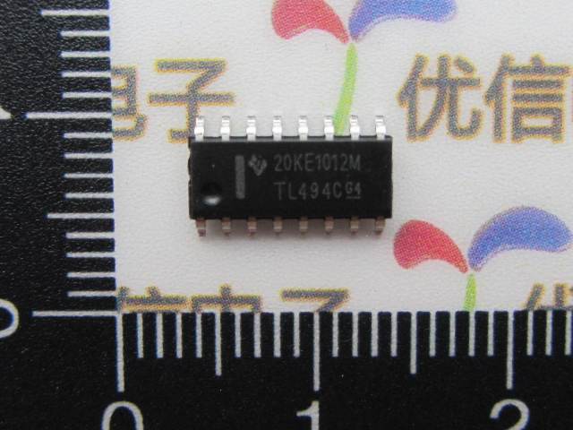
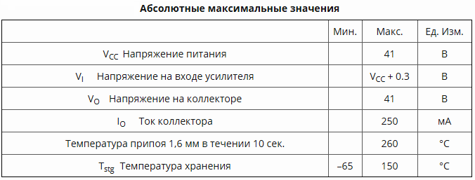
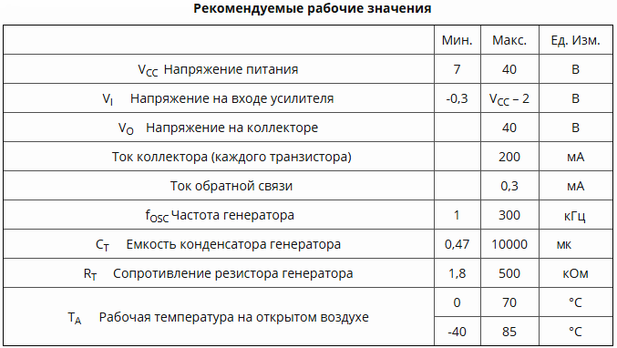
Let's start with the 494th chip. Its technical characteristics:
Pinout TL494:
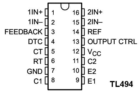
In this specific example, you can see most of the conclusions described above:
1. Non-inverting input of the first error comparator
2. Inverting input of the first error comparator
3. Feedback input
4. Dead time adjustment input
5. Output for connecting an external timing capacitor
6. Output for connecting a timing resistor
7. The total output of the chip, minus power
8. The output of the collector of the first output transistor
9. The output of the emitter of the first output transistor
10. The output of the emitter of the second output transistor
11. The output of the collector of the second output transistor
12. Power supply input
13. The input select one-stroke or push-pull mode of operation of the chip
14. The output of the built-in reference voltage source 5 volts
15. Inverting input of the second error comparator
16. Non-inverting input of the second error comparator
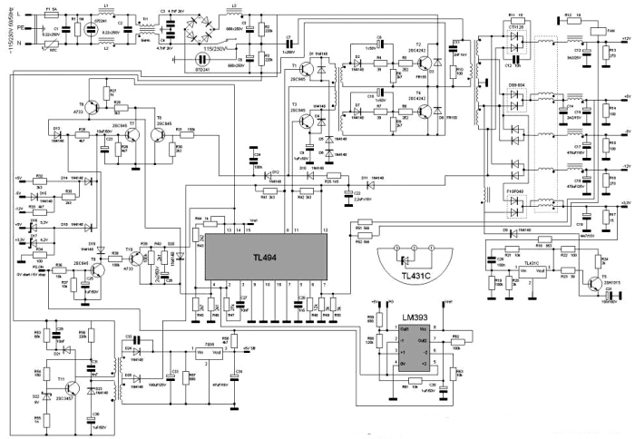
The figure below shows an example of a computer power supply on this chip.
UC3843 - Overview
Another popular PWM is the 3843 chip - it also builds computer and not only power supplies. Its pinout is located below, as you can observe, it has only 8 conclusions, but it performs the same functions as the previous IC.
Interesting:
It happens UC3843 and in the 14-foot case, but are much less common. Pay attention to the marking - additional conclusions are either duplicated or not used (NC).
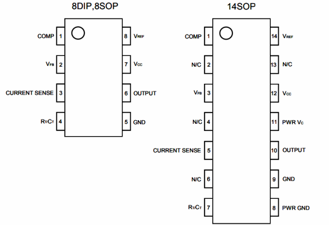
We decipher the purpose of the conclusions:
1. Comparator input (error amplifier).
2. Feedback voltage input. This voltage is compared to the reference voltage inside the IC.
3. Current sensor. It is connected to a resistor standing in between the power transistor and the common wire. It is necessary for protection against overloads.
4. The timing RC circuit. With its help, the operating frequency of the IC is set.
5. General.
6. Exit. Control voltage. It is connected to the gate of the transistor, here is a push-pull output stage for controlling a single-cycle converter (one transistor), which can be seen in the figure below.
7. The voltage of the microcircuit.
8. The output of the reference voltage source (5V, 50 mA).
Its internal structure.
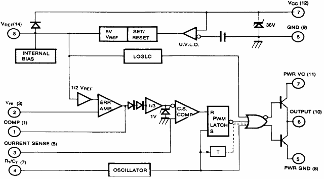
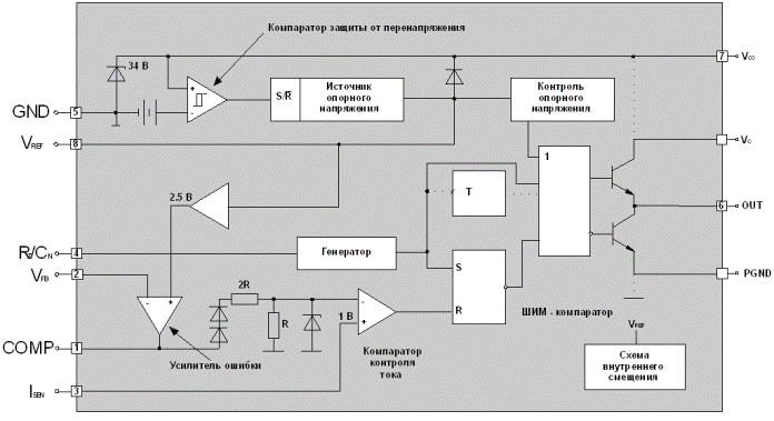
You can make sure that in many ways it is similar to other PWM controllers.
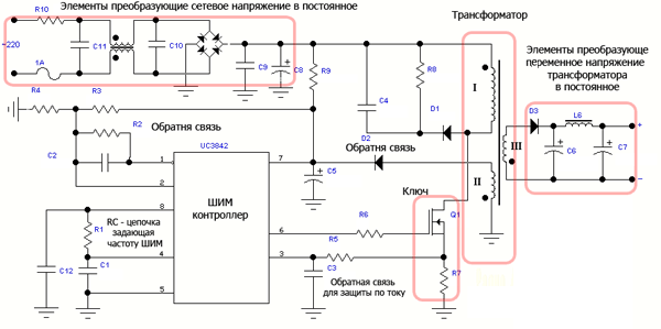
Simple power supply circuit on the UC3842
PWM with integrated power switch
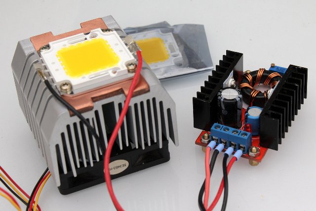
PWM controllers with a built-in power switch are used both in transformer switching power supplies and in transformerless DC-DC converters Buck, Boost, and Buck-Boost.
Perhaps one of the most successful examples is the common LM2596 microcircuit, on the basis of which you can find a ton of converters on the market, as shown below.

Such a microcircuit contains all the technical solutions described above, and instead of the output stage on low-power switches, a power switch is built into it that can withstand current up to 3A. The internal structure of such a converter is shown below.
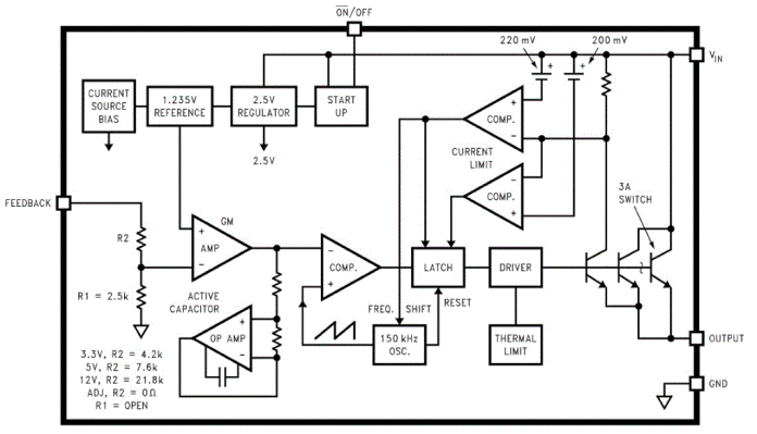
You can make sure that in essence there are no special differences from those considered in it.
And here is an example transformer power supply for led strip on such a controller, as you can see, there is no power switch, but only a 5L0380R chip with four pins. It follows that in certain tasks the complex circuitry and flexibility of the TL494 is simply not needed. This is true for low-power power supplies, where there are no special requirements for noise and interference, and the output ripple can be suppressed by an LC filter. This is a power supply for LED strips, laptops, DVD players and more.
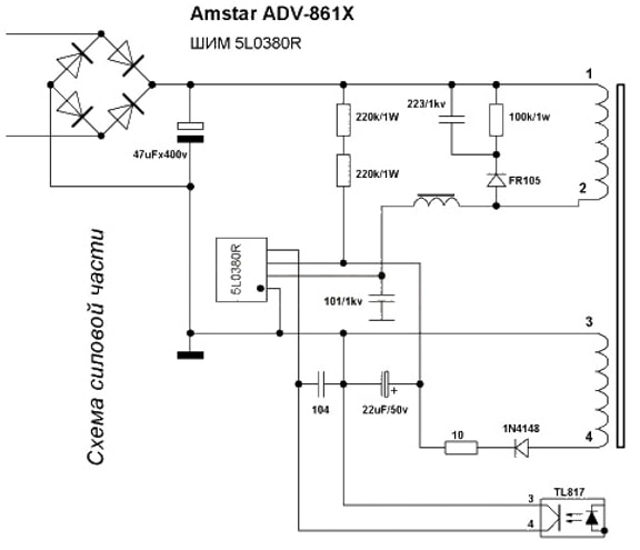
Conclusion
At the beginning of the article, it was said that a PWM controller is a device that simulates the average voltage value by changing the pulse width based on the signal from the feedback circuit. I note that the names and classification of each author are often different, sometimes a simple PWM voltage regulator is called a PWM controller, and the family of electronic circuits described in this article is called "Integrated Subsystem for Stabilized Pulse Converters". From the name, the essence does not change, but disputes and misunderstandings arise.
See also at i.electricianexp.com
:

