Categories: Featured Articles » Practical Electronics
Number of views: 8430
Comments on the article: 0
Schmitt trigger - general view
During the design of the pulse circuit, the developer may need a threshold device that could form a pure rectangular signal with certain values of high and low voltage levels from the input signal of a non-rectangular shape (for example, sawtooth or sinusoidal).
The Schmitt trigger, a circuit with a pair of stable output states, which under the action of the input signal, replace each other in a jump, fits well, that is, the output is a rectangular signal.

A characteristic feature of the Schmitt trigger is the presence of a certain range between the voltage levels for the input signal, when the output voltage of the input signal is switched over at the output of this trigger from a low level to a high one and vice versa.
This property of a Schmitt trigger is called hysteresis, and the portion of the characteristic between threshold input values is called the hysteresis region. The difference between the upper and lower threshold values for the Schmitt trigger input determines the width of its hysteresis region, which serves as a measure of the sensitivity of the trigger. The wider the hysteresis region - the less sensitive the Schmitt trigger, the narrower the hysteresis region - the higher its sensitivity.
Schmitt triggers are available in the form of specialized microcircuits, where several separate triggers can be located inside one housing at once. Such microcircuits have a certain normalized switching threshold, and give steep fronts at the output, despite the input signal that is far from a rectangular shape. In addition, the Schmitt trigger can also be built on the basis of logical elements, in which case the developer has the opportunity to very accurately set and adjust the width of the hysteresis region of his threshold device.
Pay attention to the figure, and more closely consider the principle of the Schmitt trigger.

Here is a schematic illustration of a trigger element, as well as its transfer and time characteristics. As you can see, when the input signal level Uin is lower than the lower threshold Ufor.n, the Schmitt trigger output also has, accordingly, a low voltage level U0 close to zero.
In the process of increasing the voltage of the input signal Uin, its value first reaches the lower boundary of the hysteresis region Uпор.н, the lower threshold, while the output, as before, does not change anything. And even when the input voltage Uin goes into the hysteresis region, and for some time is inside it, then the output still does not happen - the output is still low voltage U0.
But as soon as the level of the input voltage Uin is compared with the upper threshold of the hysteresis region Ufor.in (response area) - the trigger output jumps into the state of a high voltage level U1. If the input voltage Uin continues to increase further (within the limits allowed for the microcircuit), the output voltage Uout will not change anymore, since one of two stable states is reached - a high level of U1.
Now, let's say that the input voltage Uin began to decrease. When returning to the hysteresis region, no changes occur at the output; the level is still high U1. But as soon as the voltage of the input signal Uin equals the lower boundary of the hysteresis region Uпн.н - the Schmitt trigger output jumps into the state with a low voltage level U0. The work of the Schmitt trigger is based on this.
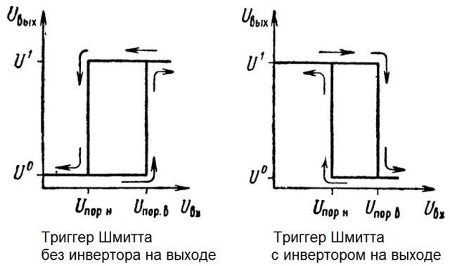
Sometimes Schmitt triggers prove to be useful, where the logic element “I” is implemented inside the microcircuit, and the inverter “NOT” is installed at the output (Schmitt inverting trigger).In this case, the transfer characteristic will look the other way around: when the voltage goes beyond the upper boundary of the hysteresis region, a low level appears at the output of the Schmitt trigger, and when it returns below the hysteresis region, a high level appears at the output. This is practically an AND-NOT element with hysteresis.

Schmitt trigger can be assembled and on an operational amplifier (op amp). Let's look at one of the options for its implementation in general terms. The inverting input of the op-amp is grounded, and the input signal is fed through the resistor R1 to the non-inverting input of the op-amp. The output of the op-amp along the feedback chain through the resistor R2 is connected to the non-inverting input of the op-amp. Rectangular voltage is removed from the op amp output.
The voltage at the output of the operational amplifier is traditionally determined by the formula Uout = K * Ua. Usually Uout.max is equal to the op-amp supply voltage (let us denote it by beech E), and K is the opamp gain, it is on the order of 1,000,000. The output voltage can vary from + E to -E. Here we will not go into particular details, and to simplify the understanding, we will consider a vivid example where the input resistor and the resistor in the feedback circuit are equal to each other: R1 = R2.
So, at the very beginning, when Uin = 0, and therefore Ua = 0, then Uout = 0, since the voltage at the non-inverting input of the op-amp does not exceed the voltage at its inverting input.
If now Uvh is slightly increased, then Ua will also slightly increase. Then Uout will increase significantly (in accordance with the value of K), since the voltage at the non-inverting input of the op-amp will exceed the voltage at its inverting input, which, as we decided, is grounded. Then, due to the fact that the point Ua is between the resistors connected according to the above diagram, at the point Ua the voltage will increase significantly, it will become approximately Uout / 2, and due to the avalanche of positive feedback, a stable voltage Uout (equal to the supply voltage OS = E). Thus, the op-amp went into a stable state with a high output voltage level. Moreover, Ua = (E + Uin) / 2.
If in this state we begin to reduce Uin, then even when it becomes equal to zero, then at the point Ua it will still be E / 2, and at the output of the op-amp there will still be a high level voltage Uout = E.

Only when Uin becomes equal to -E, only then Ua becomes equal to zero, and the op-amp output goes into a state with a low voltage level (-E). In this case, a feedback avalanche will again arise - now Uout = -E, Ua = (Uin-E) / 2, and this is much lower than at the non-inverting input of the op-amp. The trigger has entered a steady state with a low output level. In order for the op amp output to return to a high state now, it is necessary that Uin again becomes equal to E, which will cause another avalanche of feedback. Return to the zero point will no longer occur.
See also at i.electricianexp.com
: