Categories: Featured Articles » Practical Electronics
Number of views: 77792
Comments on the article: 0
Logic chips. Part 6
 IN previous parts of the article were considered the simplest devices on the logical elements 2I-NOT. This is a self-oscillating multivibrator and one-shot. Let's see what can be created on their basis.
Each of these devices can be used in various designs as master oscillators and pulse shapers of the required duration. Given the fact that the article is for guidance only, and not a description of any specific complex circuit, we restrict ourselves to a few simple devices using the above schemes.
Simple multivibrator circuits
A multivibrator is a fairly versatile device, so its use is very diverse. In the fourth part of the article, a multivibrator circuit based on three logical elements was shown. In order not to look for this part, the circuit is shown again in Figure 1.
The oscillation frequency at the ratings indicated on the diagram will be about 1 Hz. By supplementing such a multivibrator with an LED indicator, you can get a simple light pulse generator. If the transistor is taken sufficiently powerful, for example, KT972, it is quite possible to make a small garland for a small Christmas tree. By connecting a DEM-4m telephone capsule instead of an LED, you can hear clicks when switching the multivibrator. Such a device can be used as a metronome when learning to play musical instruments.
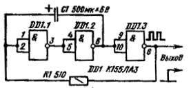
Figure 1. Multivibrator with three elements.
Based on a multivibrator, it is very simple to make an audio frequency generator. To do this, it is necessary that the capacitor be 1 μF, and use a variable resistance of 1.5 ... 2.2 KΩ as resistor R1. Such a generator, of course, will not block the entire sound range, but within certain limits the oscillation frequency can be changed. If you need a generator with a wider frequency range, this can be done by changing the capacitance of the capacitor using a switch.
Intermittent Sound Generator
As an example of using a multivibrator, we can recall a circuit that emits an intermittent sound signal. To create it, you will need two multivibrators already. In this scheme, multivibrators on two logical elements, which allows you to assemble such a generator on just one chip. Its circuit is shown in Figure 2.
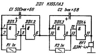
Figure 2. Intermittent beep generator.
The generator on the elements DD1.3 and DD1.4 generates sound frequency oscillations that are reproduced by the DEM-4m telephone capsule. Instead, you can use any with a winding resistance of about 600 ohms. With the ratings C2 and R2 indicated on the diagram, the frequency of sound vibrations is about 1000 Hz. But the sound will be heard only at the time when at the output 6 of the multivibrator on the elements DD1.1 and DD1.2 there will be a high level that will allow the multivibrator to work on the elements DD1.3, DD1.4. In the case when the output of the first multivibrator low level of the second multivibrator is stopped, there is no sound in the telephone capsule.
To check the operation of the sound generator, the 10th output of the DD1.3 element can be disconnected from the output 6 of DD1.2. In this case, a continuous sound signal should sound (do not forget that if the input of the logic element is not connected anywhere, then its state is considered as a high level).
If the 10th pin is connected to a common wire, for example, a wire jumper, then the sound in the phone will stop. (The same can be done without breaking the connection of the tenth output). This experience suggests that the sound signal is heard only when the output 6 of the DD1.2 element is high. Thus, the first multivibrator clocks the second. A similar scheme can be applied, for example, in alarm devices.
In general, a wire jumper connected to a common wire is widely used in the study and repair of digital circuits as a low-level signal. We can say that this is a classic of the genre. Fears of using such a method of “burning” are completely in vain. Moreover, not only the inputs, but also the outputs of digital microcircuits of any series can be “planted” on the “ground”. This is equivalent to an open output transistor or logic zero level, low level.
In contrast to what has just been said, IT IS COMPLETELY IMPOSSIBLE TO CONNECT THE MICROCIRCUITS TO THE + 5V CIRCUIT: if the output transistor is open at this time (all voltage of the power supply will be applied to the collector - emitter section of the open output transistor), the microcircuit will fail. Considering that all digital circuits do not stand still, but do something all the time, work in a pulsed mode, the output transistor will not have to open for a long time.
A probe for repairing radio equipment
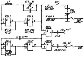
Using the logical elements 2I-NOT you can create a simple generator for tuning and repairing radios. At its output, it is possible to obtain oscillations of the sound frequency (RF), and the radio frequency (RF) oscillations modulated by the RF. The generator circuit is shown in Figure 3.
Figure 3. Generator for checking receivers.
On the elements DD1.3 and DD1.4 a multivibrator already familiar to us is assembled. With its help, vibrations of the sound frequency are generated, which are used through the inverter DD2.2 and capacitor C5 through connector XA1 to test the low-frequency amplifier.
The high-frequency oscillation generator is made on the elements DD1.1 and DD1.2. This is also a familiar multivibrator, only here a new element appeared - inductor L1 connected in series with capacitors C1 and C2. the frequency of this generator is mainly determined by the parameters of the coil L1 and can be adjusted to a small extent by capacitor C1.
On the element DD2.1 assembled a radio frequency mixer, which is fed to input 1, and to input 2 the frequency of the audio range is applied. Here, the sound frequency clocks the radio frequency in exactly the same way as in the intermittent sound signal circuit in Figure 2: the radio frequency voltage at terminal 3 of the DD2.1 element appears at the moment when the output level 11 of the DD1.4 element is high.
To obtain a radio frequency in the range of 3 ... 7 MHz, the L1 coil can be wound on a frame with a diameter of 8 mm. Inside the coil, insert a piece of the rod from a magnetic antenna made of ferrite grade F600NM. Coil L1 contains 50 ... 60 turns of wire PEV-2 0.2 ... 0.3 mm. The design of the probe is arbitrary.
It is better to use a probe generator to power stabilized voltage sourcebut you can galvanic battery.
Single vibrator application
As the simplest application of a single vibrator, a light signaling device can be called. On its basis, you can create a target for shooting tennis balls. The circuit of the light signaling device is shown in Figure 4.
Figure 4. Light signaling device.
The target itself can be quite large (cardboard or plywood), and its “apple” is a metal plate with a diameter of about 80 mm. In the circuit diagram, this is contact SF1. When hit in the center of the target, the contacts close very briefly, so the blinking of the bulb may not be noticed. In order to prevent such a situation, a single-shot is used in this case: from a short starting pulse, the bulb goes out for at least a second. In this case, the trigger pulse is elongated.
If you want the lamp not to go out when hit, but rather to flash, you should use a KT814 transistor in the indicator circuit by interchanging the collector and emitter outputs. With this connection, you can omit the resistor in the base circuit of the transistor.
As a single-pulse generator, a single-shot is often used in the repair of digital technology to test the performance of both individual microcircuits and entire cascades.This will be discussed later. Also, not a single switch, or as it is called, an analog frequency meter, can do without a single vibrator.
Simple frequency meter
On the four logical elements of the K155LA3 chip, you can assemble a simple frequency meter that allows you to measure signals with a frequency of 20 ... 20,000 Hz. In order to be able to measure the frequency of a signal of any shape, for example, a sinusoid, it must be converted into rectangular pulses. Typically, this transformation is done using a Schmitt trigger. If I may say so, he converts the “impulses” of the sine wave with gentle fronts into rectangles with steep fronts and recessions. Schmitt trigger has a trigger threshold. If the input signal is below this threshold, there will be no pulse sequence at the output of the trigger.
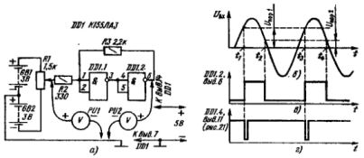
Familiarity with the work of the Schmitt trigger can begin with a simple experiment. The scheme of its holding is shown in Figure 5.
Figure 5. Schmitt trigger and graphs of his work.
To simulate the input sinusoidal signal, galvanic batteries GB1 and GB2 are used: moving the variable resistor R1 slider to the top position in the circuit simulates a positive half-wave of a sine wave, and moving down negative.
The experiment should begin with the fact that by rotating the engine of the variable resistor R1, set zero voltage on it, naturally controlling it with a voltmeter. In this position, the output of the element DD1.1 is a single state, a high level, and the output of the element DD1.2 is logic zero. This is the initial state in the absence of a signal.
Connect a voltmeter to the output of the DD1.2 element. As it was written above, at the exit we will see a low level. If now it is enough to slowly turn the variable resistor slider all the way up according to the scheme, and then down all the way to the stop and back at the output DD1.2, the device will show the element switching from low to high level and vice versa. In other words, the output DD1.2 contains rectangular pulses of positive polarity.
The operation of such a Schmitt trigger is illustrated by the graph in Figure 5b. A sine wave at the input of a Schmitt trigger is obtained by rotating a variable resistor. Its amplitude is up to 3V.
As long as the voltage of the positive half-wave does not exceed the threshold (Uпор1), a logic zero (initial state) is stored at the output of the device. When the input voltage increases by rotating the variable resistor at time t1, the input voltage reaches the threshold voltage (about 1.7 V).
Both elements will switch to the opposite initial state: at the output of the device (element DD1.2) there will be a high level voltage. A further increase in the input voltage, up to the amplitude value (3V), does not lead to a change in the output state of the device.
Now let's rotate the variable resistor in the opposite direction. The device will switch to the initial state when the input voltage drops to the second, lower, threshold voltage Uпор2, as shown in the graph. Thus, the output of the device is again set to logical zero.
A distinctive feature of the Schmitt trigger is the presence of these two threshold levels. They caused the hysteresis of the Schmitt trigger. The width of the hysteresis loop is set by the selection of the resistor R3, although not in very large limits.
Further rotation of the variable resistor down the circuit forms a negative half-wave of a sine wave at the input of the device. However, the input diodes installed inside the microcircuit simply short the negative half-wave of the input signal to a common wire. Therefore, the negative signal does not affect the operation of the device.
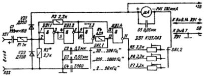
Figure 6. Frequency meter circuit.
Figure 6 shows a diagram of a simple frequency meter made on just one K155LA3 chip. On the elements DD1.1 and DD1.2, a Schmitt trigger is assembled, with the device and the operation of which we just met. The remaining two elements of the microcircuit are used to construct the measuring pulse shaper.The fact is that the duration of the rectangular pulses at the output of the Schmitt trigger depends on the frequency of the measured signal. In this form, anything will be measured, but not the frequency.
To the Schmitt trigger we already knew, a few more elements were added. At the input, capacitor C1 is installed. Its task is to skip sound frequency oscillations at the input of the frequency meter, because the frequency meter is designed to work in this range, and to block the passage of the constant component of the signal.
The diode VD1 is designed to limit the level of the positive half-wave to the voltage level of the power source, and VD2 cuts the negative half-waves of the input signal. In principle, the internal protective diode of the microcircuit can quite cope with this task, so VD2 can not be installed. Therefore, the input voltage of such a frequency meter is within 3 ... 8 V. To increase the sensitivity of the device, an amplifier can be installed at the input.
Pulses of positive polarity generated from the input signal by a Schmitt trigger are fed to the input of the measuring pulse shaper made on the elements DD1.3 and DD1.4.
When low voltage appears at the input of element DD1.3, it will switch to unity. Therefore, through it and the resistor R4 will be charged one of the capacitors C2 ... C4. In this case, the voltage at the lower input of the DD1.4 element will increase and, in the end, will reach a high level. But, despite this, the element DD1.4 remains in the state of a logical unit, since there is still a logical zero from the output of the Schmitt trigger on its upper input (DD1.2 output 6). Therefore, a very insignificant current flows through the measuring device PA1, the arrow of the device practically does not deviate.
The appearance of a logical unit at the output of the Schmitt trigger will switch the element DD1.4 to the state of logical zero. Therefore, a current limited by the resistance of resistors R5 ... R7 flows through the pointer device PA1.
The same unit at the output of the Schmitt trigger will switch the DD1.3 element to the zero state. In this case, the capacitor of the shaper begins to discharge. Reducing the voltage on it will lead to the fact that the element DD1.4 is again set to the state of a logical unit, thereby ending the formation of a low-level pulse. The position of the measuring pulse relative to the measured signal is shown in Figure 5d.
For each measurement limit, the duration of the measuring pulse is constant over the entire range, therefore, the angle of deviation of the arrow of the microammeter depends only on the repetition rate of this measuring pulse itself.
For different frequencies, the duration of the measuring pulse is different. For higher frequencies, the measuring pulse should be short, and for low frequencies, a bit large. Therefore, to ensure measurements in the entire range of sound frequencies, three time-setting capacitors C2 ... C4 are used. With a capacitor capacity of 0.2 μF, frequencies of 20 ... 200 Hz are measured, 0.02 μF - 200 ... 2000 Hz, and with a capacitance of 2000 pF 2 ... 20 KHz.
Calibration of the frequency meter is most easily done using a sound generator, starting from the lowest frequency range. To do this, apply a signal with a frequency of 20 Hz to the input and mark the position of the arrow on the scale.
After that, apply a signal with a frequency of 200 Hz, and turn the resistor R5 to set the arrow to the last division of the scale. When supplying frequencies of 30, 40, 50 ... 190 Hz, mark the position of the arrow on the scale. Similarly, tuning is performed in the remaining ranges. It is possible that a more accurate selection of capacitors C3 and C4 will be needed so that the beginning of the scale coincides with the 200 Hz mark in the first range.
On the descriptions of these simple constructions, let me finish this part of the article. In the next part, we will talk about triggers and counters based on them. Without this, the story about logic circuits would be incomplete.
Boris Aladyshkin
Continuation of the article: Logic chips. Part 7. Triggers. RS - trigger
See also at bgv.electricianexp.com
:

