Categories: Practical Electronics, Novice electricians
Number of views: 114666
Comments on the article: 4
Logic chips. Part 8. D - trigger
 The article describes the D-trigger, its operation in various modes, a simple and intuitive technique for studying the principle of action.
In the previous part of the article, the study of triggers was started. The RS trigger is considered the simplest in this family, which was described in the seventh part of the article. D and JK triggers are more widely used in electronics devices. According to the meaning of the action, they, like RS trigger, are also devices with two stable states at the output, but have a more complex logic of the input signals.
It should be noted that all of the above will be true not only for K155 series chips, and for other series of logic circuits, for example, K561 and K176. And not only with regard to triggers, all logic chips also work exactly, the difference is only in the electrical parameters of the signals - voltage levels and operating frequencies, power consumption and load capacity.
D trigger
There are several modifications of D-flip-flops in the K155 series of chips, however, the K155TM2 chip is the most common. In one 14-pin package there are two independent D-flip-flops. The only thing that unites them is a common power circuit. Each trigger has four logic level inputs and, accordingly, two outputs. This is a direct and inverse output, with which we are already familiar from the story about the RS-trigger. Here they perform the same function. Figure 1 shows a D-trigger.
There are also microcircuits containing four D-flip-flops in one housing: these are microcircuits such as K155TM5 and K155TM7. Sometimes in the literature they are called four-digit registers.
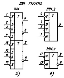
Figure 1. Chip K155TM2.
Figure 1a shows the entire microcircuit in the form as it is usually shown in reference books. In fact, on the diagrams each trigger located in the housing can be depicted away from its “partner”, while the drawing may not show conclusions that are simply not used in this circuit, although in fact they are. An example of such an outline of a D-trigger is shown in Figure 1b.
Consider in more detail the input signals. This will be done using a trigger with pins 1 ... 6 as an example. Accordingly, all of the above will be true with respect to another trigger (with pin numbers 8 ... 13).
Signals R and S perform the same function as similar RS signals of a trigger: when a logic zero level is applied to input S, the trigger is set to a single state. This means that a logical unit will appear on the direct output (pin 5). If now apply a logical zero to the R-input, the trigger is reset. This means that at the direct output (pin 5), the logic zero level will appear, and at the inverse (pin 6) there will be a logical unit.
In general, when one speaks about the state of a trigger, it means the state of its direct output: if the trigger is installed, then its direct output is at a high level (logical unit). Accordingly, it is understood that on the inverse output everything is exactly the opposite, therefore, the inverse output is often not mentioned when considering the operation of the circuit.
A logical unit can be supplied to the inputs R and S as much as desired: the state of the trigger does not change. This suggests that the inputs are R and S low. That is why the RS inputs start with a small circle, which indicates that the working signal level is low or, which is the same, inverse. Such a small circle in the input signals can be found not only in triggers, but also in the image of some other microcircuits, for example, decoders or multiplexers, which also indicates that the working level of this signal is a low level. This is a general rule for all graphic symbols of microcircuits.
In addition to RS inputs, the D-trigger also has a D data input, from English Data (data), and a synchronization input C from the English Clock (pulse, strobe). Using these inputs, you can make a trigger work either as a memory element or as a counting trigger. In order to understand the operation of the D-trigger, it is better to assemble a small circuit and carry out simple experiments.
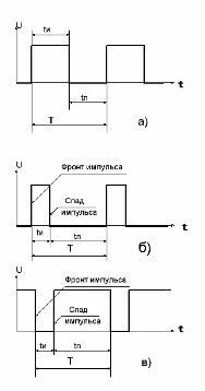
Pay attention to the image of input C: the right-hand end of this output in the figure ends with a small inclined line in the direction from left - up - to right. This feature indicates that the trigger switching over the input C occurs at the moment of transition of the input signal from zero to one. Figure 3 shows a possible pulse shape at input C.
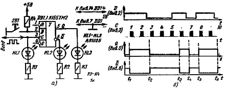
In order to more thoroughly understand the operation of the D - trigger, it is best to assemble the circuit, as shown in Figure 2.
Figure 2. Scheme for studying the operation of the D - trigger.
Figure 3. Pulse options at input C.
For clarity, the trigger is connected to its outputs (pins 5 and 6) LED indicators. We connect the same indicator to input C. Input D, through a 1 kΩ resistor, is connected to the +5 V power supply bus, and, as shown in the diagram, the SB1 button. After the circuit is assembled, we will check the installation quality, and then you can turn on the power.
Work D trigger on RS inputs
When turning on, one of the LEDs HL2 or HL3 must be lit. Suppose that it is HL3, therefore, when turned on, the trigger is set to one, although it can also be set to zero. The low-level input signals to the RS inputs will be supplied using a piece of flexible conductor connected to a common wire.
First, let's try to apply a low level to input S, just closing pin 4 to the common wire. What will happen? At the outputs of the trigger, the signals will remain in the same state as they were when turned on. Why? Everything is very simple: the trigger is already in a single state or installed, and the supply of a control signal to input S simply confirms this trigger state, the state does not change. This mode of operation for the trigger is not at all harmful and is often found in the operation of real circuits.
Now, using the same wire, we will apply a low level to input R. The result will not be long in coming: the trigger will switch to the low level, or, as they say, it will be reset. Repeated and subsequent supply of a low level to input R will also simply confirm the state, this time zero, in the same way as described above for input S. From this state, it can be deduced either by supplying a low level to input S, or combination of signals at inputs C and D.
It should be noted that sometimes a D-trigger can be used simply as an RS-trigger, that is, inputs C and D are not used. In this case, to increase the noise immunity, they should be connected to the +5 V bus through resistors with a resistance of 1 KOhm, or connected to a common wire.
Trigger operation on inputs C and D
Suppose that the trigger is currently installed, so the HL3 LED is lit. What happens if you press the SB1 button? Absolutely nothing, the state of the trigger output signals will not change. If now to reset the trigger at the input R, the LED HL2 will light, and HL3 will turn off. Pressing the SB1 button in this case will not change the trigger state. This suggests that there are no clock pulses at input C.
Now let's try to apply clock pulses to input C. The easiest way to do this is by assembling a rectangular pulse generator, already familiar to us from the previous parts of the article. Its circuit is shown in Figure 4.
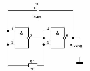
Figure 4. Clock generator.
In order to observe the operation of the circuit visually, the frequency of the generator must be small, with the details indicated on the circuit it is about 1 Hz, that is, 1 oscillation (pulse) per second. The frequency of the generator can be changed by selecting capacitor C1. The status of input C is indicated by LED HL1: the LED is lit - at the input C, the level is high, if it is off, the level is low.At the moment of ignition of the LED HL1 at the input C, a positive voltage drop is formed (from low to high). It is this transition that makes the D trigger trigger on input C, and not the presence of a high or low voltage level at this input. This should be remembered, and monitor the behavior of the trigger exactly at the moment of formation of the pulse front.
If the pulse generator is connected to input C and the power is turned on, the trigger will be set to one with the first pulse, subsequent pulses of the trigger state will not change. All of the above is true for the case when the switch SB1 is in the position shown in the figure.
Now let's switch SB1 to the lower position according to the circuit, thereby applying a low level to input D. The very first impulse that came from the generator will put the trigger in a state of logical zero or the trigger will be reset. The HL2 LED will tell us about this. Subsequent pulses at input C also do not change the state of the trigger.
Figure 2b shows the timing diagram of the trigger operation for CD inputs. It is assumed that the state of input D changes as shown in the figure, and periodic clock pulses arrive at input C.
The first pulse at input C sets the trigger to a single state (pin 5), and the second pulse of the trigger state does not change, because at the input C the level remains high so far.
The state of input D between the second and third clock pulses changes from a high level to a low one, as can be seen in Figure 2. But the trigger switches to the zero state only at the beginning of the third clock pulse. The fourth and fifth pulses at the input C of the trigger state do not change.
It should be noted that the signal at input D changed its value from low to high during a clock pulse at input C. However, the trigger did not change state, since the positive edge of the clock pulse was earlier than the level change by inlet D.
In a single state, the trigger will be switched only by the sixth pulse, more precisely by its front. The seventh pulse will reset the trigger, since a high level has already been established at the input D during its positive edge. The following impulses work in exactly the same way, so readers can deal with them on their own.
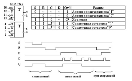
Another timing diagram is shown in Figure 5.
Figure 5. Complete timing diagram of D trigger operation.
The figure shows that the trigger can work in three modes, two of which have already been discussed above. In the figure, these are asynchronous and synchronous modes. The prevailing mode is of the greatest interest in the time diagram: it is clear that during the low level at the input R, the trigger state does not change at the inputs C and D, which indicates that the RS inputs are priority. Figure 5 also shows the truth table for the D - trigger.
From the foregoing, the following conclusions can be drawn: each positive pulse difference at input C sets the trigger to the state that at that moment was at input D, or simply transfers its state to the direct output of trigger Q. The negative difference on the pulse at input C has no effect on The trigger state does not render.
Figure 3 shows the possible pulse shapes at the C input: it is a meander (3a), short high-level pulses, or positive (3b), short low-level pulses (negative) (3c). In any case, the trigger is triggered by a positive difference.
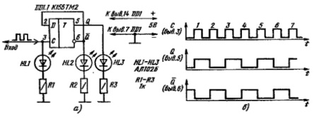
In some cases, it will be the front of the impulse, and in others its decline. This circumstance should be taken into account when developing and analyzing circuits on D - triggers. Operation of the D - trigger in counting mode One of the main purposes of the D - trigger is its use in counting mode. In order to make it work as a pulse counter, it is enough to apply a signal from its own inverse output to input D. Such a connection is shown in Figure 6.
Figure 6. Operation of the D - trigger in counting mode.
In this mode, upon the arrival of each pulse at input C, the trigger will change its state to the opposite, as shown in the time diagram. And the explanation for this is the simplest and most logical: the state at the input D is always opposite, inverse, with respect to the direct output. Therefore, in the light of the previous consideration of the trigger operation, its inverse state is transferred to the direct output. One trigger, albeit in counting mode, does not count much, only up to two: 0..1 and again 0..1, and so on.
To get a counter capable of counting, you really need to connect several triggers in counter mode in series. This will be discussed later in a separate article. In addition, you should pay attention to the fact that the pulses at the output of the trigger have a frequency exactly two times lower than the input at the input C. This property is used in cases where it is necessary to divide the signal frequency by a factor of two: 2, 4 , 8, 16, 32 and so on.
The shape of the pulses after the division by the trigger is always a meander, even in the case of very short input pulses at the input C. This is the end of the story about the possibilities of using the D trigger. The next part of the article will talk about the use of JK type triggers.
Continuation of the article: Logic chips. Part 9. JK trigger
See also at bgv.electricianexp.com
:

