Categories: Featured Articles » Practical Electronics
Number of views: 16666
Comments on the article: 1
Indicator of short-term voltage dips
 A simple circuit for determining short “dips” in mains voltage.
Domestic power supply
Everyone knows about the low quality of domestic energy supply, and a lot has been said about it. Instead of a voltage tolerance of +/- 10 percent, which is 180 ... 240 V, the mains voltage can "float" in the range of 160 ... 260 or more V.
Such slow voltage changes are quite successfully handled by AC voltage stabilizers based on autotransformers, for example, Resanta. Such stabilizers are designed mainly for such equipment as a refrigerator, washing machine, electric stove.
Electronic stabilizers
Modern electronic household equipment does not require such stabilizers, since all voltage stabilization is carried out, as a rule, by internal semiconductor stabilizers.
In a very wide range of input mains voltages, switching power supplies are capable of working. Now almost all electronic equipment is equipped with such sources. For example, many modern TVs are fully operational in the voltage range of 100 ... 280 V.
Impulse noise
But, unfortunately, in addition to such slow changes in the mains voltage, which can be seen with the naked eye by flashing lights, there are also short-term “dips”. They are of a pulsed nature, and not a single stabilizer is able to protect against accidental impulse noise.
Such “failures”, invisible even by the flashing of lighting, can bring a lot of troubles. Suddenly, for no reason, a recently acquired computer randomly reboots, the washing machine always worked diligently, starts an unfinished wash cycle again, and the microwave also goes astray from the set program.
Some devices, such as stand-by televisions, turn on spontaneously, or switch channels themselves during operation. It seems that the electronic equipment is gradually becoming unusable. Or maybe it's time to carry it in for repair?
Network Failure Indicator
The device described below can inform about such unpleasant situations - an indicator of short-term “dips” in the mains voltage. Indeed, if suddenly your computer started to "reboot" on its own, and at that time an indicator sound was heard, which detected a "failure" of the mains voltage, then with a fair amount of certainty we can say that the computer is not to blame. Even uninterruptible power supplies with impulse noise do not always cope.
The indicator diagram is quite simple and is shown in Figure 1.

Figure 1. Indicator of short “dips” in mains voltage.
As can be seen from the figure, the circuit diagram of the device is quite simple, contains a small number of parts, which, moreover, are not expensive and are not a deficit. Therefore, to repeat the scheme, too high qualifications are not required: if you know how to hold a soldering iron in your hands, then there should not be any special problems.
Circuit work
The scheme works as follows. On the elements VD2, R3 ... R5, C2 and C4 assembled a voltage sensor. It is with its help that “failures” in the network are determined. When the mains voltage is applied, capacitors C2 and C4 will quickly charge to the voltage indicated on the diagram. Therefore, at the input DD1 there is a logical unit.
The power supply unit is assembled on the elements VD1, VD3, R2, C3, C6. It should be noted that the capacitor C6 charges up to 9V for a long enough time - about thirty seconds. This is due to the large time constant of the chain R2, C3, C6.Therefore, when the device is first turned on, a low voltage level is set at the output of the DD1.1 element.
Capacitor C5 was discharged when turned on, that is, it had a low logic level. As can be seen from the diagram, the capacitor C5 through the resistor R8 is connected to the input of the Schmitt trigger, made on the elements DD1.2 ... DD1.4. therefore, the output of the Schmitt trigger will also have a low voltage level. Therefore, the HL1 LED will be off, and the HA1 sound emitter will be silent. To increase the load capacity of the output stage, a parallel connection of the elements DD1.3 and DD1.4 is used.
It should be noted here that such a connection is permissible only if both logical elements belong to one housing of the microcircuit and have identical parameters. Such a connection of elements located in different buildings is unacceptable.
The above state of the indicator will remain until there is a "failure" of the mains voltage. In the case of a significant decrease in the voltage of the network with a duration of at least 60 ms, the capacitors C2 and C4 discharge.
In other words, a low level will appear at the input of the DD1.1 element, which will lead to a high level at the output of DD1.1. This high level leads to the charge through the V5 diode of the capacitor C5, that is, the appearance of a high level at the input of the Schmitt trigger and, accordingly, the same level at its output. (The logic of the Schmitt trigger was described in one of the articles from the series "Logic chips").
The modern element base makes it possible to significantly simplify the circuit design of many devices. In this case, a sound emitter with a built-in generator is used. Therefore, to obtain sound, it is sufficient to apply a constant voltage to the emitter.
In this case, it will be a high voltage from the output of the Schmitt trigger. (When the emitters were without a built-in generator, it had to be assembled also on microcircuits.) In parallel with the sound emitter, the HL1 LED was installed, which provides a light indication of a “failure”.
In this state, the Schmitt trigger will remain for some time after the "failure" has ended. This time is due to the charge of the capacitor C5 and at the values of the elements indicated on the diagram will be approximately 1 second. We can say that the “failure” in time simply stretches.
After the discharge of the capacitor C5, the device returns to the tracking mode of the voltage state of the network. To prevent false alarms of the device from interference at the input, an anti-interference filter L1, C1, R1 is installed.
A few words about the details and design
In addition to the elements indicated in the diagram, the following replacements are possible. The K561LA7 chip can be replaced without altering the circuit and the board on the K561LE5, or with an import analog of any of the CMOS series. It is not recommended to use K176 series microcircuits that do not have built-in protective diodes at the inputs, since the input voltage of the microcircuit in this design exceeds the supply voltage. This circumstance can lead to the failure of the K176 series microcircuit due to the "thyristor effect".
The Zener diode VD3 can be replaced by any low-power one with a stabilization voltage of about 9 V. Instead of KD521 diodes, any pulsed silicon diodes, for example KD503, KD510, KD522, or imported 1N4148, can be replaced, KD243 diodes can be replaced with 1N4007.
High-voltage ceramic capacitor C1 type K15-5. Instead, it is possible to use a film capacitor for an operating voltage of at least 630V, though due to some decrease in reliability. The film should also be a capacitor C2. Electrolytic capacitors are best used imported.
The LED indicated on the diagram can be replaced by almost any domestic or imported, preferably red. The sound emitter can be replaced with any of the EFM series: EFM - 250, EFM - 472A.
The entire indicator is mounted on the circuit board shown in Figure 2.
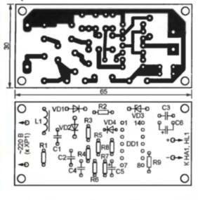
All details except the LED and the sound emitter are installed on the board. The board can be installed in a separate plastic box of suitable sizes, or, if space permits, directly in the filter housing - extension cord.
Setting up the device boils down to selecting the capacitance of capacitors C2 and C4. It is more convenient to select the capacitance of the capacitor C4. This is done as follows: its capacity decreases until the voltage ripple at the input of the DD1.1 element causes the device to trip. Upon achieving this result, replace the capacitor C4 with a capacitor with a capacity 30 percent more than the selected one.
You can check the correct operation of the indicator by connecting a halogen lamp with a power of at least one and a half to two kilowatts to the same outlet. At the moment of switching on, an indicator signal should be heard - increased currents affect the moment the lamps are turned on. On this, the adjustment of the indicator can be considered complete.
Boris Aladyshkin
See also at bgv.electricianexp.com
: