Categories: Practical Electronics, Novice electricians
Number of views: 65691
Comments on the article: 3
Logic chips. Part 7. Triggers. RS - trigger
 Electronic devices with two stable output states are called triggers. A trigger is translated into one of the stable states by input pulses.
A similar formulation is given, as a rule, in all technical literature. For the one who came across it for the first time, it may not be entirely clear. What are these two states, and why are they called stable?
The easiest way to explain this is with a simple and accessible example. A fairly close and understandable analogue can be an ordinary light bulb with a switch. There are two states here: on - off. For a trigger, these states are high, low. It is also sometimes said, on - off, installed - reset.
In order to light or turn off the light bulb, just touch the switch. In order for the bulb to continue to burn, it is not at all necessary to hold the switch with your finger: the bulb will burn indefinitely.
In other words, she is in a steady state. It can only be brought out of this state by turning it off, using the same switch. Or, in other words, move to another stable state. This state will also be stable, that is, it remains indefinitely, until it is turned on.
As another similar example, we can recall conventional two-button magnetic starter: pressed the black button - the electric motor turned on, pressed the red - turned off. At the same time, you should pay attention to the fact that repeated pressing of the “Start” button (if the engine is already on) will in no case increase its speed. In the same way, you can press the Stop button when the motor is stopped: it is simply a confirmation of the Stop state.
In these examples, the pulsed nature of the input signal is clearly visible (pressing a switch or button). There are also two “on - off” states, each of which is stable: it continues until the input signal is affected. Closest to the considered examples is the RS - trigger.
RS - trigger
Of all the types of triggers, RS is a trigger, both by the principle of operation and by circuitry, the simplest. Previously, when triggers were performed on discrete parts (transistors, resistors, capacitors, diodes), they said that a trigger is a two-stage amplifier, covered by positive feedback. We will not consider this option.
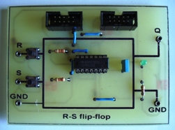
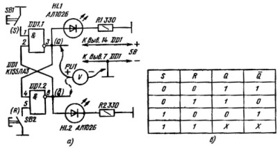
The trigger from logical elements 2I - NOT microchips K155LA3. A diagram of such a trigger is shown in Figure 1.
Figure 1. RS - trigger on elements 2I - NOT.
The trigger is obtained by cross feedback from the output to the input between two logic elements. Such a trigger has two outputs and two independent inputs. One of the inputs (the upper one according to the scheme) is called S from the English SET - set, the other input is called R from the English RESET - reset. Often these inputs and, accordingly, signals are called simply turn on and off.
In addition to two RS inputs, the trigger has two outputs. Most often, the outputs are indicated on the circuits by the letter Q. One of the outputs is called direct, and the other is inverse. The letter Q denoting the inverse output is underlined above. The designation / Q or –Q is also allowed. In our scheme, the direct output is the 3th output of the DD1.1 element, and the inverse output is the 6th output of the DD1.2 element.
As input signals, just buttons are used, by pressing of which the trigger is transferred to the corresponding state. In real circuits, input signals can be supplied from the outputs of the microcircuits. For educational experiments, the buttons can be replaced simply with a piece of wire.
It should be noted right away that everything in this circuit is arbitrary: the input signals do not belong to the specific legs of the microcircuit, as indicated in the diagram. In this case, R and S can be interchanged, and the location of the direct and inverse outputs will change. Here, everything just depends on the imagination of the developer of a particular scheme.
Two LEDs are used to indicate the trigger status: one of them lights when the output is at a high level. The other will be repaid. LEDs can not be installed, the status of the trigger outputs can be monitored by a conventional voltmeter, although this will not be very convenient and clear.
After the circuit is assembled on a breadboard, you should check the correct installation, and then turn it on. When turned on, one of the LEDs will light up. Which one, it is impossible to say in advance, since everything is determined by unstable transients during switching on and the spread of the parameters of logical elements.
Suppose that the HL1 LED lights up, which indicates that the direct output of the Q trigger is high. In this case, they say that the trigger is installed. The inverse output / Q will be correspondingly low (the signal level at the inverse output is always opposite to the level at the direct output).
All discussions about the state of the trigger are relative to the state of the direct output. If the direct output is high, the trigger is set (on, is in a single state), and if the direct output is low, it is considered that the trigger is reset (off, in the zero state). As mentioned above, the state of the inverse output is always opposite to the direct one.
So when you turn on the power, the HL1 LED lights up, which indicates a high level on the direct output. The HL2 LED will be off - the trigger is in a single state.
If in this state of the trigger to press the button SB1, then nothing will happen - the LED HL1 will continue to light and HL2 is off. Thus, pressing the SB1 button simply confirmed the single state of the trigger.
The trigger can be removed from this state only by pressing the SB2 button: the LED HL1 will turn off, and HL2 will turn on. As in the previous case, repeated pressing or holding the SB2 button for a long time will not be able to change this state. In this state, the circuit will remain indefinitely, namely until the SB1 button is pressed, or until the power is turned off.
And what happens if you press both buttons at once? Nothing terrible, apart from the fact that the trigger state will be undefined, since at both outputs there is a level of a logical unit. By the logic of the trigger, this state is considered prohibited, therefore, it is unacceptable.
If the logic level is present at both inputs, then the trigger state does not change. This mode is called information storage mode. Therefore, the RS - trigger is often used in storage devices, for example, in various types of static RAM chips.
This whole story is presented in the truth table of the RS-trigger, shown in Figure 1b. A similar version of the RS-trigger is called asynchronous, because it does not require any additional signals that allow or prohibit the operation of RS inputs.
Quite often, the RS-trigger is used as a suppressor of bounce of mechanical contacts if it is necessary to count the number of pulses using an electronic counter. Such counters are also performed on triggers. Typically, these are D or JK triggers, which will be discussed in the next part of the article.
Boris Aladyshkin
Continuation of the article: Logic chips. Part 8. D - trigger
See also at bgv.electricianexp.com
:

