Categories: Practical Electronics, Novice electricians
Number of views: 74031
Comments on the article: 0
Logic chips. Part 9. JK trigger
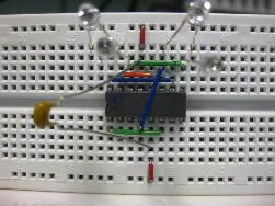 A story about JK trigger and simple experiments to study his work.
In the previous parts of the article, triggers such as RS and D were described. This story will be incomplete if you do not mention Jk trigger. Just like D trigger It has advanced input logic. In the 155 series, this is a K155TV1 chip manufactured in the DIP-14 package. Its pinout, or as they say now, the pinout (from the English PIN - pin) is shown in Figure 1a. Foreign analogues SN7472N, SN7472J.
If any conclusion is not used in a particular scheme, then it is completely acceptable to simply not show it, as shown in Figure 1b.
Description and purpose of conclusions
The K155TV1 trigger has direct and inverse outputs. In the figure, these are conclusions 8 and 6, respectively. Their purpose is the same as for the previously considered triggers of type D and RS. Inverse exit begins in a small circle.
On inputs R and S, the trigger works just like a simple RS trigger. The working level for these inputs is low, which is indicated by circles at the base of the terminals. As with the D - trigger, these inputs are priority: the appearance and holding of a low level on one of them prohibits the rest of the inputs, and a short negative pulse will transfer the trigger to the corresponding state until the next pulse at input C.
Input C is clocked. When the trigger operates in the counting mode, it plays the role of the information one — it is precisely on it that counting pulses arrive. In the mode of receiving and storing information, it serves as a clock, its purpose is similar to a similar input of a D-trigger, but the logic of operation is somewhat different and is determined by the state of the JK inputs.
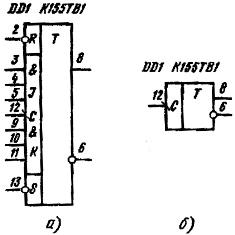
Figure 1. The pinout of the K155TV1 chip.
J and K are trigger control inputs. They are combined according to scheme 3I, which is indicated by the symbol & - logical I. on the graphic symbol. Quite often, these inputs simply connect together in the circuits, it turns out that it has one J and one K input. Some series of microcircuits also have JK triggers, they are also called TB1, but unlike the 155 series, they have one J and K input. The logic of work on these inputs is exactly the same as that of K155TV1, but you do not need to collect 3 high-level logic signals together. An example of such microcircuits can serve, for example, K176TV1, K561TV1, K1564TV1.
Learning the logic of the JK trigger
To learn more about the operation of the JK trigger, you just need to turn it on, as in the previous article, on the breadboard and manually submit the input signals. Indeed, you must admit that you can memorize a self-instruction manual on playing the guitar or button accordion, but without picking up the instrument, you won’t learn to play. Also in the case of microcircuits: until you conduct the simplest experiments, it will be difficult to understand the meaning of the work.
As input signals, in the same way as when studying the D trigger, we will use a wire jumper connected to a common wire.
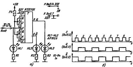
The circuit for testing the JK trigger K155TV1 is shown in Figure 2.
Figure 2. Test JK trigger K155TV1.
The supply voltage is supplied as usual to the 14th and 7th conclusions of the microcircuit, which is indicated on the diagram in the form of conductors with arrows.
For visual observation of the state of the trigger, LED indicators are connected to its outputs, direct and inverse. The same indicator is connected to input C. The LED glow indicates the presence of a logical unit level (2.4 ... 5V) at this output. At the input C, the level of the output signal of the pulse generator connected to the input C will be displayed. Of course, the state of the inputs and outputs at such a low frequency is quite possible to observe with an ordinary voltmeter, but this is not very convenient.
JK trigger operation on RS - inputs
Although the circuit turned out to be very simple before switching on, as usual, you should check it for errors, short circuits and breaks: even just turning on the power in the opposite direction can make the microcircuit unusable. This rule should be remembered and applied in all such cases, even if it is just an electrical circuit without semiconductor devices.
So turn it on. When you first turn on, one of the LEDs at the output must be lit, which is unknown. This is due to transients when turned on. Now we will apply a low logic level, using the aforementioned wire jumper, alternately to the R and S inputs. In this case, the LEDs at the output should alternately switch, indicating the state of the trigger. This mode of operation is called asynchronous - it does not require additional strobe (enable, clock) signals.
It is not necessary to apply simultaneously a low level directly to the R and S inputs: this state is considered forbidden for the trigger. Although it will not lead to irreversible consequences in the form of an output of the microcircuit, the state of the outputs in this case will be unknown, which does not correspond to the logic of the trigger. If everything is fine, then you can go to experiments on studying the operation of a trigger on JK inputs.
What happens if a low wire is applied to the JK inputs with a jumper wire? Nothing at all: the trigger will store the previous state, which will be visible by the glow of the indicators. In order for these inputs to affect the state of the trigger, it is necessary to apply pulses to the input C from the generator, the circuit of which is shown in Figure 3. To assemble it, an additional K155LA3 chip is needed. The pulse repetition rate and duration should be such that visual monitoring of the trigger states is possible.
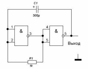
Figure 3. Clock generator.
JK trigger operation in counting mode
If the JK inputs are connected, as shown in Figure 2a, then the trigger will work in counting mode: the state of the trigger will change with each input pulse. The resistor R4 is shown in the diagram with a dotted line - you can not put it, because unconnected inputs are still in the state of a logical unit. The main purpose of this resistor is to protect against interference through the JK inputs.
The timing diagram of the JK trigger is shown in Figure 2b, and it is very similar to a similar diagram for the D - trigger. The main difference is that the trigger state does not change due to a positive level difference at input C, but a negative one - when the level of the input pulse changes from a high level to a low one.
It is easy to see that the frequency of the pulses at the output of the trigger is exactly two times lower than the frequency of the input pulses. Therefore, triggers in counting mode are often used as frequency dividers by two. Two triggers included in series will divide the frequency into four, and three triggers will already be divided into eight, and so on according to the power of 2.
If a frequency divider with an odd division coefficient is required, then several triggers with feedbacks are used, but this will be discussed in the next part of the article on counters and pulse shapers.
From the foregoing, we can conclude: if the JK inputs are simultaneously in the state of a logical unit (high level), the trigger works in counting mode. This means that for each negative level difference at input C, the trigger state changes to the opposite.
Trigger operation on JK inputs
What happens if a logical zero level is present at the JK inputs? To check this, it is enough to connect at least one JK input (recall that K155TV1 has 3 J and 3 K inputs, combined according to 3I circuit) to a common wire. But you can connect to the common wire and all the inputs of JK, this is already unprincipled. According to the LED indicators, we see that the clock pulses are coming, and the trigger state does not change.In a state when the logic zero on J and K inputs, JK - trigger is in the information storage mode.
It remains to consider two cases. Case one is when input J is high and input K is low. In this situation, the trigger at input C is set to a single state - the HL3 indicator connected to the direct output of the trigger lights up. HL2, of course, is repaid.
If the state of the JK inputs does not change in the future, then each pulse at the input C will also tend to set the trigger to a single state, although it is already in it. In this case, they say that at the input C, the previous trigger state in this case is simply confirmed.
The second case is when the input J is zero and the input K is one. In this state, at the JK inputs, the first pulse at input C, the trigger will be set to zero (reset) - the HL3 indicator will turn off and HL2 will turn on. If the state of the JK inputs does not change, then the input C also confirms the state, as described above, only this time zero.
So, to make it easier to remember, to summarize: two units at the inputs of JK is a counting mode. It is understood that condition 3I is fulfilled for the JK inputs: one on all three inputs J, and one on all three inputs K.
Two zeros on JK inputs - information storage mode: pulses at input C of the trigger state cannot be changed. To obtain such a state, it is enough that at least one input J And at least one input K has a logic zero level.
In the case when all three J - inputs are high, the trigger is set to a single state. In this case, at least one of the 3 inputs of K must have a low level.
To reset a trigger, zero must be present on at least one of the inputs J, and one must be held on all three inputs K.
Everything that was written above can be found in the truth table for the K155TV1 trigger, which is shown in Figure 4.
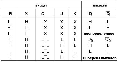
Figure 4. The truth table for the K155TV1 chip.
Triggers of various types are also used as elements of counting devices, or simply counters, as well as pulse shapers. This will be discussed in the next part of the article on logic circuits.
Continuation of the article: Logic chips. Part 10. How to get rid of the bounce of contacts
See also at bgv.electricianexp.com
:

