Categories: Featured Articles » Practical Electronics
Number of views: 25599
Comments on the article: 0
Simple transformerless pulse voltage converters
Many beginner hams find it difficult to determine the type of power supply, but it's not so difficult. The main methods of voltage conversion are to use one of two circuitry options:
-
Transformer;
-
Transformerless power supplies.
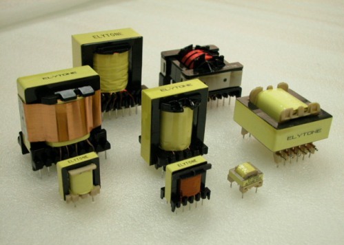
In turn, transformers differ in the type of circuit:
-
Mains, with a transformer operating at a frequency of 50 Hz;
-
Pulse, with a transformer operating at high frequencies (tens of thousands of Hz).
Pulse circuits of power supplies can increase the overall efficiency of the final product, by avoiding static losses on linear stabilizers and other elements.
Transformerless circuits
If there is a need for power from a 220 V household power supply, the simplest devices can be turned on from power supplies using ballast elements to reduce voltage. A widely known example of such a power source is a ballast capacitor circuit.
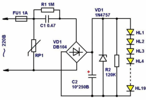
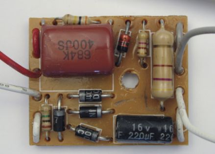
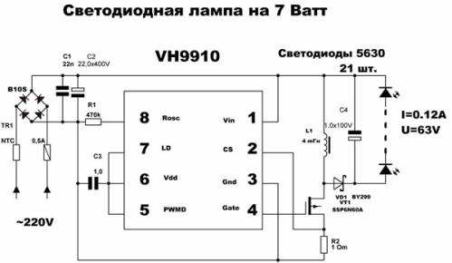
However, there are a number of drivers with built-in PWM controller and a power key to build a transformerless pulse buck converter, these are very common in LED light bulbs and other technology.
In the case of power from a direct current source, for example, batteries or other galvanic batteries, use:
-
Linear voltage stabilizer (integral KEN or L78xx type stabilizer with or without pass-through transistor, parametric stabilizer from zener diode and transistor)
-
Pulse converter (step-down - BUCK, step-up - BOOST, or step-up - BUCK-BOOST)
The advantage of transformerless power supplies and converters are as follows:
-
There is no need to wind the transformer, conversion is carried out by the throttle and keys;
-
A consequence of the previous are the small dimensions of the power sources.
Disadvantages:
-
The absence of galvanic isolation, in case of malfunctions of the keys leads to the appearance of voltage of the primary power source. This is critical especially if its role is played by a 220 V network;
-
Danger of electric shock, as a result of galvanic coupling;
-
The large dimensions of the inductor on high-power converters cast doubt on the feasibility of using this topology of power supplies. With comparable weight and size indicators, you can use a transformer, galvanically isolated converter.
The main varieties of switching voltage converters
In domestic literature, the abbreviation "IPPN" is often found, which stands for: Pulse Step-down (or step-up, or both) Voltage Converter
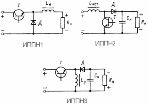
As a basis, three basic schemes can be distinguished.
1. IPPN1 - Step-down converter, in the English literature - BUCK DC CONVERTER or Step-down.
2. IPPN2 - Boost converter, in English literature - BOOST DC CONVERTER or Step-up.
3. IPPN3 - Inverting converter with the possibility of both increasing and decreasing voltage, BUCK-BOOST DC CONVERTER.
How does a pulsed buck converter work?
Let's start by considering the principle of operation of the first scheme - IPPN1.
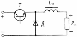
In the scheme, two power circuits can be distinguished:
1. "+" from the power source is supplied through a private key (transistor of any type of the corresponding conductivity) to Lн (storage choke), then the current flows through the load to the "-" power source.
2. The second circuit is formed from diode Д, throttle Lн and connected load Rн.
When the key is closed, the current passes along the primary circuit, current flows through the inductor, and energy is accumulated in its magnetic field. When we turn off (open) the key, the energy stored in the coil is dissipated into the load, while the current flows through the second circuit.
The voltage at the output (load) of such a converter is
Uout = Uin * Ku
Ku is the conversion coefficient, which depends on the duty cycle of the control pulses of the power switch.
Ku = Uout / Uin
The duty cycle "D" is the ratio of the time when the key is open to the PWM period. "D" can take values from 0 to 1.
IMPORTANT: For STI1 Ku = D. This means that the regulation limits of this stabilizer are approximately equal - 0 ... Uout.
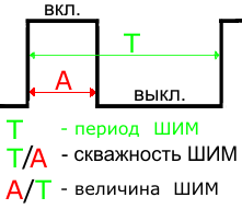
The output voltage of such a converter is similar in polarity to the input voltage.
How does a pulse boost voltage converter
IPPN2 - is able to increase the voltage from the supply voltage to a value tens of times higher than it. Schematically, it consists of the same elements as the previous one.
Any converter of this type has in its composition three main active ingredients:
-
Managed Key (Bipolar, Field, IGBT, MOSFET Transistors);
-
Uncontrolled key (rectifier diode);
-
Cumulative inductance.
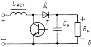
The current always flows through the inductance, only its magnitude changes.
In order to understand the principle of operation of this converter, you need to remember the switching law for the inductor: "The current through the inductor cannot change instantly."
This is caused by a phenomenon such as self-induction EMF or counter-EMF. Since the electromagnetic field of the inductance prevents an abrupt change in current, the coil can be represented as a power source. Then in this circuit, when the key is closed through the coil, a current of large magnitude begins to flow, but, as has been said sharply, it cannot increase.
Counter-EMF is a phenomenon when at the ends of the coil an EMF appears opposite to what is applied. If you present this in the diagram for clarity, you will have to imagine the inductance coil as a source of EMF.
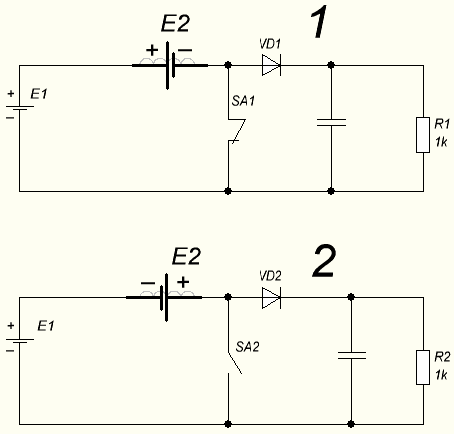
The number “1” indicates the state of the circuit when the key is closed. Please note that the power source and the symbol EMF coils are connected in series with the positive terminals, i.e. their EMF values are subtracted. In this case, the inductance prevents the passage of electric current, or rather slows down its growth. As it grows, after a certain constant time interval, the value of the counter-EMF decreases, and the current through the inductance increases.
Lyrical digression:
The value of the EMF of self-induction, like any other EMF, is measured in Volts.
During this period of time, the main current flows along the circuit: power source-inductance-closed key.
When the key SA opens, circuit 2. Current begins to flow along such a circuit: power source-inductance-diode-load. Since the load resistance, often much more than the channel resistance of a closed transistor. In this case, again - the current flowing through the inductance cannot change abruptly, the inductance always seeks to maintain the direction and magnitude of the current, therefore, the counter-EMF appears again, but in reverse polarity.
Notice how in the second diagram the poles of the Power Source and the EMF source replacing the coil are connected. They are connected in series by opposite poles, and the values of these EMF are added up.
Thus, an increase in voltage occurs.
During the process of storing inductance energy, the load is powered by energy that was previously stored in the smoothing capacitor.
The conversion coefficient in IPPN2 is
Ku = 1 / (1-D)
As can be seen from the formula - the larger D is the duty cycle, the greater the output voltage. The polarity of the output power is the same as the input for this type of converter.
How does the inverting voltage converter
The inverting voltage converter is a rather interesting device, because it can work both in the voltage lowering mode and in the boost mode. However, it is worth considering that the polarity of its output voltage is opposite to the input, i.e. positive potential is on the common wire.
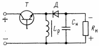
Inverting is also noticeable in the direction in which the diode D. is turned on. The principle of operation is a bit similar to IPPN2. At the time when the key T is closed, the process of accumulating inductance energy occurs, the power from the source does not get into the load due to diode D. When the key is closed, the inductance energy begins to dissipate in the load.
The current continues to flow through the inductance, an EMF of self-induction occurs, directed in such a way that a polarity opposite to the primary power source is formed at the ends of the coil. Those. in the junction of the emitter of the transistor (drain, if field effect transistor), the cathode of the diode and the end of the coil winding forms a negative potential. At the opposite end, respectively, is positive.
The conversion factor IPPN3 is equal to:
Ku = D / (1-D)
By simple substitutions of the fill factor into the formula, we determine that up to a value of D of 0.5, this converter acts as a down converter, and from above - as an up converter.
How to control such a converter?
It is possible to describe all the options for constructing PWM controllers infinitely, several volumes of technical literature can be written about this. I want to limit myself to listing a few simple options:
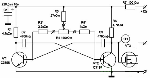
1. Assemble an asymmetric multivibrator circuit. Instead of VT3, a transistor is connected in the IPPN circuits.
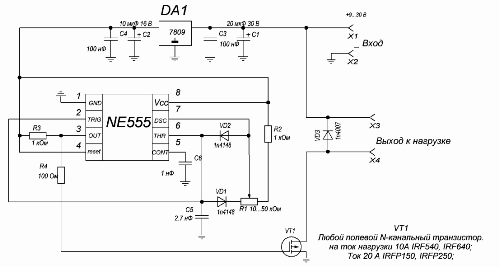
2. A slightly more complicated option, but more stable in terms of frequency, is PWM on NE555 (click on the picture to enlarge).
Make changes on the circuit, VT1 is a transistor, we change the circuit so that in its place there is an IPPN transistor.
3. Option to use microcontroller, so you can also do many additional functions, for beginners they’ll work well AVR microcontrollers. There is a wonderful video tutorial about this.
conclusions
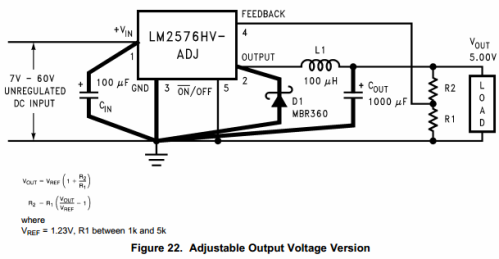
Switching voltage converters are a very important topic in the industry of power supplies for electronic equipment. Such circuits are used everywhere, and recently, with the growth of "home-made" or as it is now fashionable to call "DIY's" and the popularity of the aliexpress website, such converters have become especially popular and in demand, you can order a ready-made circuit board that has already become a classic converter for LM2596 and the like for just a couple of dollars, while you get the ability to adjust the voltage or current, or both.
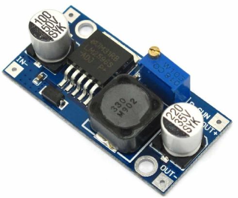
Another popular board is the mini-360
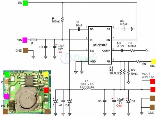
You may notice that there is no transistor in these circuits. The fact is that it is built into the chip, besides it there is a PWM controller, feedback circuits for stabilizing the output voltage, and more. However, these circuits can be amplified by installing an additional transistor.
If you are interested in designing a circuit for your needs, then you can read more about the design ratios in the following literature:
-
“Components for building power sources”, Mikhail Baburin, Alexey Pavlenko, Symmetron Group of Companies
-
"Stabilized Transistor Converters" V.S. Moin, Energoatomizdat, M. 1986.
See also at bgv.electricianexp.com
:

