Categories: Featured Articles » Practical Electronics
Number of views: 66615
Comments on the article: 1
How to make a rectifier and a simple power supply
A rectifier is a device for converting AC voltage to DC. This is one of the most common parts in electrical appliances, ranging from a hair dryer to all types of power supplies with an output DC voltage. There are different schemes of rectifiers and each of them to a certain extent copes with its task. In this article, we will talk about how to make a single-phase rectifier, and why it is needed.
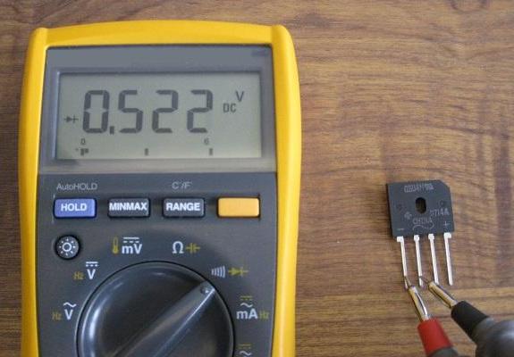
Definition
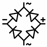 A rectifier is a device designed to convert AC to DC. The word "constant" is not entirely correct, the fact is that at the output of the rectifier, in the circuit of a sinusoidal alternating voltage, in any case there will be an unstabilized pulsating voltage. In simple words: constant in sign, but varying in magnitude.
There are two types of rectifiers:
-
Half-wave. It rectifies only one half-wave of the input voltage. Characterized by strong ripple and reduced relative to the input voltage.
-
Biannual. Accordingly, two half-waves are straightened. The ripple is lower, the voltage is higher than at the input of the rectifier - these are two main characteristics.
What does stabilized and unstabilized voltage mean?
Stabilized is a voltage that does not change in magnitude independently of either the load or the surges of the input voltage. For transformer power supplies, this is especially important because the output voltage depends on the input voltage and differs from it by the Transformation times.
Unstabilized voltage - varies depending on surges in the supply network and load characteristics. With such a power supply, due to subsidence, incorrect operation of the connected devices or their complete inoperability and failure can occur.
Output voltage
The main values of the alternating voltage are the amplitude and effective value. When they say "in the 220V network" means the current voltage.
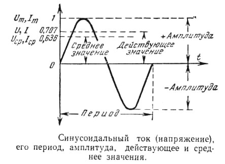
If we talk about the amplitude value, we mean how many volts are from zero to the upper point of the half-wave of a sine wave.
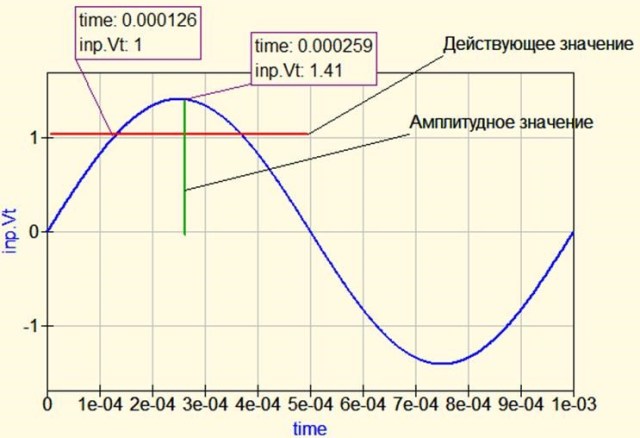
Omitting the theory and a number of formulas, we can say that current voltage 1.41 times less than amplitude. Or:
Uа = Uд * √2
The amplitude voltage in the 220V network is:
220*1.41=310
Schemes
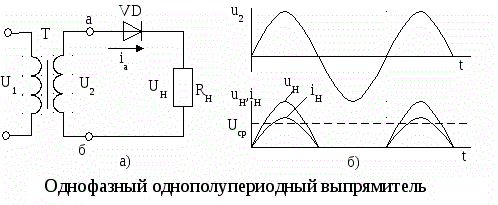
Half wave rectifier consists of one diode. He just does not miss the return half-wave. The output is a voltage with strong ripples from zero to the amplitude value of the input voltage.
Speaking in a very simple language, then in this circuit, half of the input voltage enters the load. But this is not entirely correct.
Two-half-wave circuits transmit both half-waves from the input to the load. Above in the article, the amplitude value of the voltage was mentioned, so the voltage at the output of the rectifier is the same lower in value than the active variable at the input.

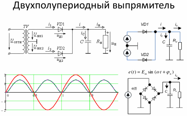
But if we smooth the ripple using capacitor, the smaller the ripples, the closer the voltage will be to the amplitude.

We will talk about smoothing ripples later. Now consider diode bridge circuit.
There are two of them:
1. Rectifier according to the Gretz scheme or diode bridge;
2. Rectifier with a midpoint.
The first scheme is more common. Consists of a diode bridge - four diodes interconnected by a “square”, and a load is connected to its shoulders. The bridge rectifier is assembled according to the scheme below:
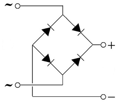
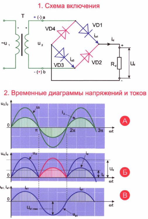
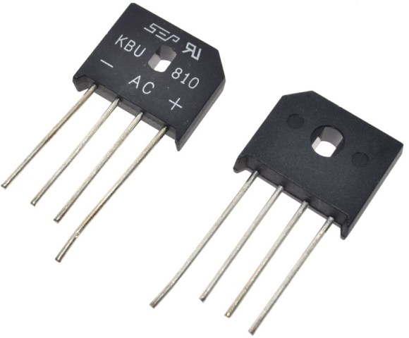
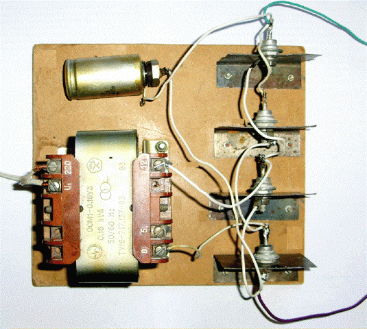
It can be connected directly to a 220V network, as is done in modern switching power supplies, or to the secondary windings of a network (50 Hz) transformer.According to this scheme, diode bridges can be assembled from discrete (separate) diodes or use a ready-made diode bridge assembly in a single housing.
The second circuit is a mid-point rectifier that cannot be connected directly to the network. Its meaning is to use a transformer with a tap from the middle.
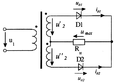
In essence, these are two half-wave rectifiers connected to the ends of the secondary winding, the load with one contact is connected to the junction point of the diodes, and the second to the tap from the middle of the windings.
Its advantage over the first circuit is a smaller number of semiconductor diodes. And the disadvantage is the use of a transformer with a midpoint or, as they call it, a branch from the middle. They are less common than conventional non-tap-type secondary transformers.
Ripple Smoothing
Ripple voltage supply is unacceptable for a number of consumers, for example, light sources and audio equipment. Moreover, the permissible pulsations of light are regulated in state and industry regulatory documents.
To smooth the pulsations, use filters - a parallel mounted capacitor, an LC filter, a variety of P and G filters ...
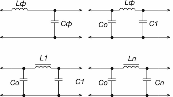
But the most common and simplest option is a capacitor installed parallel to the load. Its disadvantage is that in order to reduce ripple at a very powerful load, it will be necessary to install capacitors of very large capacity - tens of thousands of microfarads.
Its principle of operation is that the capacitor is charging, its voltage reaches amplitude, the supply voltage begins to decrease after the point of maximum amplitude, from that moment the load is powered by the capacitor. The capacitor discharges depending on the load resistance (or its equivalent resistance, if it is not resistive). The larger the capacitance - the smaller the ripple will be, if compared with a capacitor with a lower capacity connected to the same load.
In simple words: the slower the capacitor discharges, the less ripple.
The capacitor discharge rate depends on the current consumed by the load. It can be determined by the formula of the time constant:
t = RC
where R is the load resistance, and C is the capacity of the smoothing capacitor.
Thus, from a fully charged state to a fully discharged capacitor is discharged in 3-5 t. It charges at the same speed if the charge occurs through a resistor, so in our case it doesn’t matter.
It follows that in order to achieve an acceptable level of ripple (it is determined by the requirements of the load on the power source), a capacitance is needed that will be discharged over a time several times greater than t. Since the resistances of most loads are relatively small, a large capacity is needed, therefore, in order to smooth out ripples at the output of the rectifier, electrolytic capacitors, they are also called polar or polarized.
Please note that confusing the polarity of the electrolytic capacitor is highly discouraged, because this is fraught with its failure and even explosion. Modern capacitors are protected from explosion - they have a stamping on the top cover in the form of a cross, along which the case is simply cracked. But a stream of smoke will come out of the condenser, it will be bad if it gets into your eyes.
Calculation of capacity is based on what kind of ripple coefficient you need to provide. In simple terms, the ripple coefficient shows how much voltage is sagging (pulsating).
To calculate the capacity of a smoothing capacitor, you can use the approximate formula:
C = 3200 * In / Un * Kp,
Where In - load current, Un - load voltage, Kn - ripple factor.
For most types of equipment, the ripple coefficient is taken 0.01-0.001. Additionally, it is desirable to install ceramic capacitor as large a capacity as possible, for filtering from high-frequency interference.
How to make a do-it-yourself power supply?
 The simplest DC power supply consists of three elements:
1. Transformer;
2. Diode bridge;
3. Capacitor.
If you need to get a high voltage, and you neglect galvanic isolation, you can exclude the transformer from the list, then you will get a constant voltage up to 300-310V. Such a circuit is at the input of switching power supplies, for example, such as on your computer. We recently wrote a great article about them - How is a computer power supply.
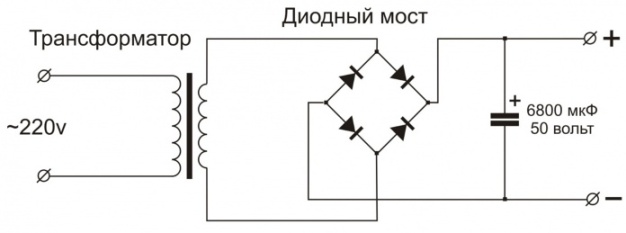
This is an unstabilized DC power supply with a smoothing capacitor. The voltage at its output is greater than the alternating voltage of the secondary winding. This means that if you have a 220/12 transformer (primary on 220V, and secondary on 12V), then at the output you will get a 15-17V constant. This value depends on the capacity of the smoothing capacitor. This circuit can be used to power any load, if it is not important for it, then the voltage can “float” when the voltage of the mains changes.
Important:
The capacitor has two main characteristics - capacitance and voltage. We figured out how to select the capacity, but not with the selection of voltage. The capacitor voltage must exceed at least half the amplitude voltage at the rectifier output. If the actual voltage on the capacitor plates exceeds the rated voltage, it is likely to fail.
Old Soviet capacitors were made with a good margin of voltage, but now everyone uses cheap electrolytes from China, where at best there is a small margin, and in the worst case, they can not withstand the specified nominal voltage. Therefore, do not save on reliability.
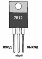

A stabilized power supply unit differs from the previous one only in the presence of a voltage (or current) stabilizer. The simplest option is to use L78xx or others. linear stabilizers, such as domestic Bank.
So you can get any voltage, the only condition when using such stabilizers is that the voltage to the stabilizer must exceed the stabilized (output) value by at least 1.5V. Consider what is written in the datasheet 12V stabilizer L7812:

The input voltage should not exceed 35V, for stabilizers from 5 to 12V, and 40V for stabilizers at 20-24V.
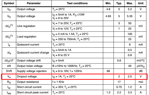
The input voltage must exceed the output voltage by 2-2.5V.
Those. for a stabilized 12V power supply with a stabilizer of the L7812 series, it is necessary that the rectified voltage lie within 14.5-35V, in order to avoid subsidence, it would be an ideal solution to use a transformer with a secondary winding to 12V.
But the output current is quite modest - only 1.5A, it can be amplified using a pass-through transistor. if you have PNP transistors, you can use this scheme:
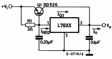
It shows only the connection of the linear stabilizer “left” part of the circuit with a transformer and rectifier is omitted.
If you have NPN transistors like KT803 / KT805 / KT808, then this one will do:
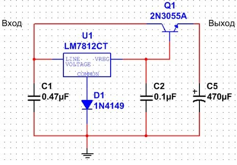
It is worth noting that in the second circuit, the output voltage will be less than the stabilization voltage by 0.6V - this is a drop at the emitter base junction, we wrote more about this in an article on bipolar transistors. To compensate for this drop, a diode D1 was introduced into the circuit.
It is possible to install two linear stabilizers in parallel, but not necessary! Due to possible deviations during manufacture, the load will be distributed unevenly and one of them may burn out due to this.
Install both the transistor and the linear stabilizer on the radiator, preferably on different radiators. They are very hot.
Adjustable Power Supplies
The simplest adjustable power supply can be made with an adjustable linear stabilizer LM317, its current is also up to 1.5 A, you can amplify the circuit with a pass-through transistor, as described above.
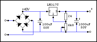
Here is a more intuitive diagram for assembling an adjustable power supply.
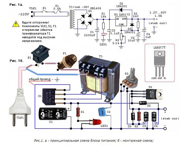
To get more current, you can use a more powerful adjustable stabilizer LM350.
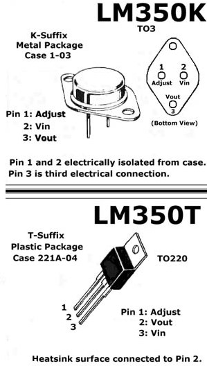
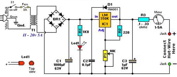
In the last two circuits, there is an on indicator that shows the presence of voltage at the output of the diode bridge, a 220V circuit breaker, and a primary fuse.
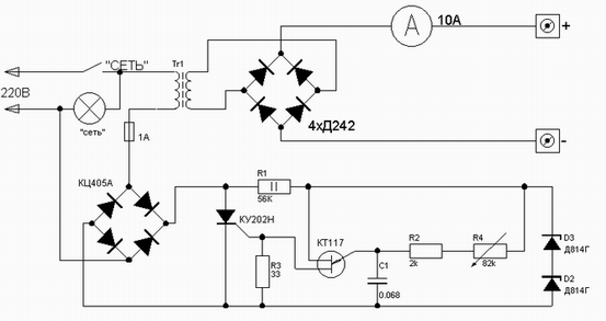
Here is an example of an adjustable battery charger with thyristor regulator in the primary winding, essentially the same adjustable power supply.
By the way, the welding current is also regulated by a similar circuit:
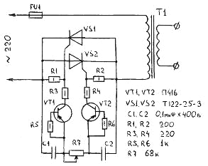
This article was laid out earlier: How to make a simple current regulator for a welding transformer
Conclusion
A rectifier is used in power supplies to produce direct current from an alternating current. Without his participation, it will not be possible to power a DC load, for example, an LED strip or a radio receiver.
Also used in a variety of chargers for car batteries, there are a number of circuits using a transformer with a group of taps from the primary winding, which are switched by a wrench switch, and only a diode bridge is installed in the secondary winding. The switch is installed on the high voltage side, since there the current is many times lower and its contacts will not burn from this.
According to the diagrams from the article, you can assemble the simplest power supply unit both for permanent work with some device and for testing your electronic home-made products.
The circuits do not differ in high efficiency, but they produce a stabilized voltage without special ripples, you should check the capacitance of the capacitors and calculate for a specific load. They are perfect for low-power audio amplifiers, and will not create an additional background. An adjustable power supply will be useful for car enthusiasts and electricians to test the generator voltage regulator relay.
An adjustable power supply is used in all areas of electronics, and if it is improved by short-circuit protection or a current stabilizer with two transistors, you will get an almost complete laboratory power supply.
See also at i.electricianexp.com
:
