Categories: Featured Articles » Novice electricians
Number of views: 10828
Comments on the article: 0
How does AC rectification
As you know, power plants produce alternating current. AC easily converts using transformers, it is transmitted through wires with minimal losses, many electric motors work on alternating current, in the end, all industrial and domestic networks today operate on alternating current.
However, for some applications, alternating current is fundamentally unsuitable. Batteries need to be charged with direct current, electrolysis plants are powered by direct current, LEDs require direct current, and there is still much more to do without direct current, not to mention the gadgets that are originally used batteries. One way or another, sometimes it is necessary to extract direct current from an alternating current by converting it, to solve this problem, they resort to rectifying the alternating current.

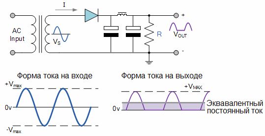
For rectification of alternating current use diode rectifiers. The simplest rectifier circuit containing just one semiconductor diodeis called a half-wave rectifier. The alternating current here passes through the primary winding of the transformer, the secondary winding of which is connected to the anode of the diode with one of its terminals and to the load circuit with the other, which, in turn, being connected to the diode's cathode, closes the secondary circuit of the transformer.
Consider what happens at the first moment of time, when a positive voltage is applied to the anode of the diode relative to its cathode, acting during the first half-period of the alternating current.
At this moment, the electrons move from the cathode to the anode of the diode, through the wire of the secondary winding of the transformer, through the inductor and then through the load - this is how the circuit closes. When the opposite half-cycle begins, electrons cannot penetrate from the anode to the cathode, therefore there is no current in the circuit during this half-period. With the onset of the next half-cycle, the process repeats.
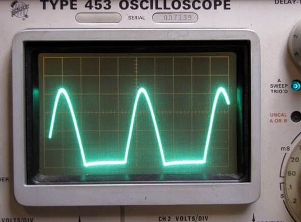
So, since the current in the circuit flows only during one of the half-periods, this type of rectification is called half-wave rectification. And due to the fact that during negative half-periods the current does not get into the load circuit, its shape turns out to be pulsating, because it acts in one direction, although it changes in magnitude.

A smoothing filter consisting of a choke (inductor) and capacitors is used in this circuit in order to reduce the ripple level on the load and make the current almost perfectly constant. The filter circuit practically does not allow the filter component to pass into the load, it passes only the constant component.

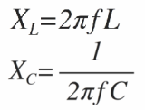
The coil has an inductive resistance, which depends on the frequency of the current, and the higher the frequency, the greater the inductive resistance of the coil, so the coil resists the alternating component of the pulsating current. The coil passes the constant component easily.
The capacitor, however, passes the variable component, but does not pass the constant, and the higher the frequency of the current, the stronger the capacitor passes it. In general, the larger the capacitance of the capacitor and the higher the inductance of the inductor coil, the less is the unnecessary component change in the direct current flowing specifically through the load.
So, when a positive half-wave of current acts in the circuit, the first capacitor is charged to the amplitude of the alternating voltage of the secondary winding (minus the voltage drop across the diode). When the negative half-wave acts, electricity does not enter the capacitor, and it, discharging to the load, maintains a constant current in it.
If there were no inductor, then since the voltage across the capacitor would decrease during this process, the current at the load would somehow have strong ripples. To reduce the ripple, a choke (coil) is added to the circuit, and even with an additional capacitor located behind it. The second capacitor takes over the current flowing through the inductor, which already contains almost no ripple.

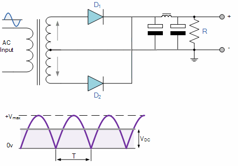
To smooth the ripple even better, use a half-wave rectifier. A half-wave rectifier can be implemented in one of two ways. It can be performed over the bridge (consisting of four diodes), or include only two diodes, but then the secondary winding of the transformer should have twice the number of turns and the output in the middle between the halves of the windings.
A half-wave rectifier operates as follows. During one of the half-periods (for example, positive), the current is directed from the anode to the cathode of the upper one according to the diode circuit, and the lower diode does not pass current at the time, it is locked (the only diode in the one-half-wave rectifier behaves the same during the negative half-wave current )
The current closes through the filter, the load, and then through the middle output to the transformer winding. When the second half-cycle occurs, the polarity of the current is such that the lower diode according to the circuit passes current through the filter and through the load, and the upper diode is locked. Next, the processes are repeated.
Since the current is supplied to the load during each of the two periods, this rectification is called half-wave rectification, and the rectifier is called a half-wave rectifier. The output pulsation is widow less than that of half-wave rectification, since the frequency of the rectified pulses is twice as high, the inductance of the inductor is twice as large, and the capacitors do not have time to significantly discharge.
In more detail, typical schemes of various rectifiers are considered here: Schemes of single-phase rectifiers
See also at i.electricianexp.com
:
