Categories: Sharing experience, Practical Electronics
Number of views: 30,040
Comments on the article: 3
How to calculate and select a quenching capacitor
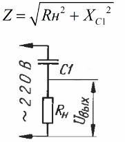
At the very beginning of the topic, regarding the selection of a quenching capacitor, we consider a circuit consisting of a resistor and a capacitor connected in series to a network. The total resistance of such a circuit will be equal to:
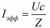
The effective value of the current, respectively, is found according to Ohm's law, the network voltage divided by the impedance of the circuit:
As a result, for the load current and input and output voltages, we obtain the following ratio:

And if the output voltage is sufficiently small, then we have the right to consider effective value of current approximately equal to:

However, let us consider from a practical point of view the issue of selecting a quenching capacitor for inclusion in the AC network of a load designed for a voltage lower than the standard mains voltage.
Suppose we have a 100 W incandescent lamp designed for a voltage of 36 volts, and for some incredible reason we need to power it from a 220 volt household network. The lamp needs an effective current equal to:

Then the capacity of the necessary quenching capacitor will be equal to:

Having such capacitor, we gain hope to get a normal glow of the lamp, we hope that at least it will not burn out. This approach, when we proceed from the effective current value, is acceptable for active loads, such as a lamp or heater.

But what if the load is non-linear and turned on through diode bridge? Suppose you need to charge a lead-acid battery. What then? Then the charging current will be pulsating for the battery, and its value will be less than the effective value:

Sometimes a radio source may find it useful a power source in which the quenching capacitor is connected in series with the diode bridge, the output of which is in turn a filter capacitor of significant capacity, to which a DC load is connected. It turns out a kind of transformerless power source with a capacitor instead of a step-down transformer:

Here, the load as a whole will be nonlinear, and the current will become far from sinusoidal, and it will be necessary to conduct calculations in a slightly different way. The fact is that a smoothing capacitor with a diode bridge and a load will externally manifest itself as a symmetrical zener diode, because ripples with a significant filter capacity will become negligible.
When the voltage on the capacitor is less than some value, the bridge will be closed, and if higher, the current will go, but the voltage at the bridge output will not increase. Consider the process in more detail with graphs:

At time t1, the mains voltage reached amplitude, capacitor C1 is also charged at this moment to the maximum possible value minus the voltage drop across the bridge, which will be approximately equal to the output voltage. The current through capacitor C1 is equal to zero at this moment. Further, the voltage in the network began to decrease, the voltage on the bridge, too, but on capacitor C1 it has not yet changed, and the current through capacitor C1 is still zero.
Further, the voltage on the bridge changes sign, trying to decrease to minus Uin, and at that moment current rushes through the capacitor C1 and through the diode bridge. Further, the voltage at the bridge output does not change, and the current in the series circuit depends on the rate of change of the supply voltage, as if only capacitor C1 is connected to the network.
When the network sinusoid reaches the opposite amplitude, the current through C1 again becomes equal to zero and the process goes in a circle, repeating every half period. Obviously, the current flows through the diode bridge only in the interval between t2 and t3, and the average current value can be calculated by determining the area of the filled figure under the sinusoid, which will be equal to:

If the output voltage of the circuit is sufficiently small, then this formula approaches the value obtained previously. If the output current is set to zero, then we get:

That is, when the load breaks, the output voltage will become equal to the network voltage !!! Therefore, such components should be used in the circuit so that each of them would withstand the amplitude of the supply voltage.
By the way, when the load current is reduced by 10%, the expression in parentheses will decrease by 10%, that is, the output voltage will increase by about 30 volts, if we initially deal with, say, 220 volts at the input and 10 volts at the output. Thus, the use of a zener diode parallel to the load is strictly necessary !!!

But what if the rectifier is half-wave? Then the current must be calculated by the following formula:

At small values of the output voltage, the load current will become half as much as when rectifying with a full bridge. And the voltage at the output without load will be twice as large, since here we are dealing with a voltage doubler.
So, the power supply with a quenching capacitor is calculated in the following order:
-
First of all, choose what the output voltage will be.
-
Then determine the maximum and minimum load currents.
-
Next, determine the maximum and minimum supply voltage.
-
If the load current is assumed to be unstable, a zener diode parallel to the load is required!
-
Finally, the capacity of the quenching capacitor is calculated.
For a circuit with half-wave rectification, for a network frequency of 50 Hz, the capacitance is found by the following formula:

The result obtained by the formula is rounded to the side of a larger nominal capacity (preferably not more than 10%).
The next step is to find the stabilization current of the zener diode for the maximum supply voltage and minimum current consumption:

For a half-wave rectification circuit, the quenching capacitor and the maximum zener current are calculated by the following formulas:

When choosing a quenching capacitor, it is better to focus on film and paper capacitors. Film capacitors of small capacity - up to 2.2 microfarads per operating voltage of 250 volts work well in these schemes when powered from a 220 volt network. If you need a large capacity (more than 10 microfarads) - it is better to choose a capacitor for an operating voltage of 500 volts.
See also at i.electricianexp.com
: