Categories: Featured Articles » Practical Electronics
Number of views: 5292
Comments on the article: 1
Bootstrap capacitor in a half-bridge control circuit
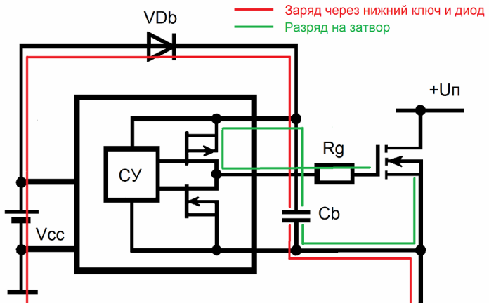
Integrated circuits - half-bridge drivers, such as, for example, IR2153 or IR2110, involve the inclusion in the general circuit of a so-called bootstrap (detached) capacitor for independent power supply to the upper key control circuit.
While the bottom key is open and conducting current, the bootstrap capacitor is connected through this open bottom key to the negative power bus, and at this time it can receive charge through the bootstrap diode directly from the driver's power source.
When the lower key is closed, the bootstrap diode stops supplying charge to the bootstrap capacitor, since the capacitor is disconnected from the negative bus at the same moment, and now can function as a floating power source for the gate control circuit of the upper half-bridge key.
Such a solution is justified, because the power often required for key management is relatively small, and the energy consumed can simply be periodically replenished from the driver’s low-voltage power supply directly during the operation of the power unit. A striking example is the output low-frequency stage of almost any low-power inverter 12-220.

As for the capacity of the bootstrap capacitor, it should be neither too large (to be able to completely recharge in time while the lower key is open) and not too small so as not only to discharge on the circuit elements ahead of time, but also be able to constantly hold a sufficient amount charge without a noticeable voltage drop, so that this charge is more than enough for the upper key control cycle.
Therefore, when calculating the minimum capacitance of a bootstrap capacitor, the following significant parameters are taken into account: the gate charge of the upper key Qg, the current consumption of the output stage of the microcircuit in the static mode Is, and the voltage drop across the bootstrap diode Vbd.
The current consumption of the output stage of the microcircuit can be taken with a margin of Is = 1mA, and the voltage drop across the diode should be taken equal to Vbd = 0.7V. As for the type of capacitor, it must be a capacitor with a minimum leakage current, otherwise the leakage current of the capacitor will also have to be taken into account. A tantalum capacitor is well suited for the bootstrap role, since capacitors of this type have the smallest leakage current from other electrolytic counterparts.

Calculation Example
Suppose we need to select a bootstrap capacitor to power the upper key control circuit of a half-bridge assembled on IRF830 transistors and operating at a frequency of 50 kHz, and the gate switch of the upper key (the control voltage taking into account the voltage drop across the diode will be 11.3 V) at this voltage 30 nC (full gate charge Qg is determined by datasheet).
Let the voltage ripple on the bootstrap capacitor not exceed dU = 10 mV. This means that the main allowable voltage change on the bootstrap capacitor in one cycle of the half-bridge operation should be brought by two main consumers: the microcircuit itself and the gate of the field pole controlled by it. Then the capacitor will be recharged through the diode.
The development cycle of the microcircuit lasts 1/50000 seconds, which means that when consumed in static mode 1 mA, the charge dissipated by the microcircuit will be equal to
Q microcircuits = 0.001 / 50000 = 20 nC.
Q gate = 30 nC.
When returning these charges, the voltage across the capacitor should not change by more than 0.010 mV. Then:
SB * dU = Q microcircuit + Q gate.
Reset = (Q circuits + Q gate) / dU.
For our example:
Cbt = 60 nl / 0.010V = 6000 nF = 6.0 uF.
We choose a capacitor with a capacity of 10 microfarads 16 V, tantalum. Some developers recommend multiplying the minimum capacitance of the capacitor by 5-15, for sure enough.As for the bootstrap diode, it must be fast-acting and withstand the maximum voltage of the power part of the half-bridge as the reverse.
See also at bgv.electricianexp.com
:
