Categories: Featured Articles » Practical Electronics
Number of views: 18803
Comments on the article: 0
Single-phase rectifiers: typical circuits, waveforms and modeling
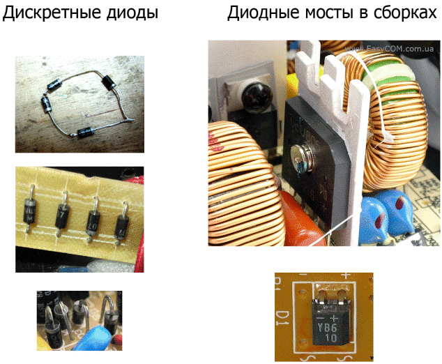
A rectifier is used in an AC circuit to convert it to DC. The most common is a rectifier assembled from semiconductor diodes. At the same time, it can be assembled from discrete (separate) diodes, or it can be in one housing (diode assembly).
Let's look at what a rectifier is, what they are, and at the end of the article we will conduct simulation in a Multisim environment. Modeling helps to fix the theory in practice, without assembly and real components, view the forms of voltages and currents in the circuit.
AC rectifier circuits
The images above show the appearance of diode bridges. But this is not the only straightening scheme. For single-phase voltage, there are three common rectification schemes:
1.1-half-period (1ph1n).
2. 2-half-period (1ph2p).
3. 2-half-period with a midpoint (1ph2p).
Half wave rectification scheme
The simplest circuit consists of only one diode, which gives a constant unstabilized ripple voltage at the output. Diodes are connected to the power circuit by a phase wire, or by one of the terminals of the transformer winding, the second end to the load, the second load pole to the neutral wire or the second terminal of the transformer winding.
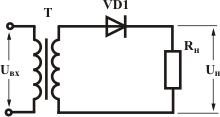
The effective value of the voltage in the load is approximately half the amplitude. The amplitude value of the voltage is the amplitude of the sine wave of the supply network in the general case for alternating current
Uampl = Uaction * √2.
For electric networks in Russia, the operating voltage of a single-phase network is 220 V, and the amplitude is approximately 311
In simple words - at the output we get ripples half a period long (20 ms for 50 Hz) from 0 V to 311 V. On average, the voltage is less than 220 volts, this is used to power consumers that are undemanding to the quality of voltage or to turn on incandescent lamps in utility rooms and utility rooms. This reduces power consumption and increases service life.
Lyrical digression:
The durability of such lamps is colossal, I came to the workshop a year ago, and the lamp was installed back in 2013, so it still shines for 12 hours every day. But such light cannot be used in workrooms, due to high ripple. Oscillograms of input and output voltages are shown below:
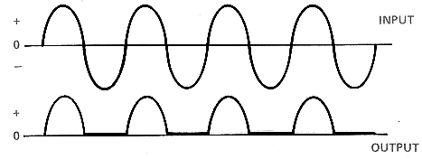
The half-wave circuit cuts off only one half-wave, which is what you see in the diagram above. Because of this power supply, we get a large ripple factor.
It is worth saying that if you change the topic a bit and switch from network rectifiers, then a half-wave circuit is widely used in pulsed circuitry, rectifying voltage pulse coil transformer secondary.
On low-power switching power supplies, this circuit is also used. This is exactly how your mobile phone charger is most likely made.
Half-wave circuit
To reduce the ripple coefficient and filter capacity, another scheme is used - two-half-cycle. It is called - diode bridge. Alternating voltage is supplied to the connection point of the opposite poles of the diodes, and constant in sign from the same name. The output voltage of such a bridge is called rectified pulsating (or not stabilized). It is this inclusion of diodes that is most common in all areas of electronics.

On the diagrams you see that both the second half-wave of the alternating voltage “flips” and enters the load. In the first half of the period, current flows through the diodes VD1-VD4, in the second through a pair of VD2-VD3.
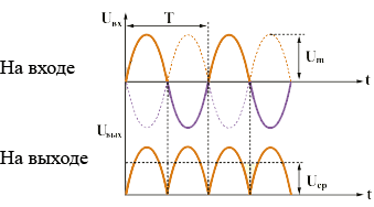
The output voltage pulsates at a frequency of 100 Hz
The second circuit is used in power supplies with a midpoint, in fact these are two half-wave combined with the secondary winding of a transformer with a midpoint. Anodes are connected to the extreme ends of the winding, cathodes are connected to one load terminal (positive), the second load terminal is connected to the tap from the middle of the winding (midpoint).
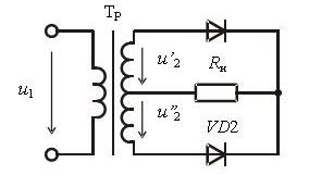
The output voltage graph is similar and we will not consider it. The only significant difference is that the current flows simultaneously through one diode, and not through a pair as in a bridge. This reduces the energy loss on the diode bridge and the excess heating of semiconductors.
Ripple factor reduction
The ripple factor is a value that reflects how much the output voltage ripples. Or vice versa - how stable and uniformly the current is supplied to the load.
To reduce the ripple coefficient in parallel with the load (the output of the diode bridge), various filters are installed. The easiest option is to install a capacitor. In order for the ripples to be as small as possible, the filter time constant R of the filter load should be an order of magnitude (or rather several) greater than the ripple period (in our case, 10 ms).
For this, either the load must have a high resistance and low current, or the capacitance of the capacitor is large enough.
The calculated ratio for selecting a capacitor is as follows:

Kp is the required ripple factor.
Kп = Uampl / Uavr
To improve a number of filter characteristics, LC circuits connected according to the D or P-filter scheme can be used, in some cases other configurations. The disadvantage of using LC filters in amateur radio practice is the need to select a filter choke. And the right one for the nominal value (inductance and current) is often not at hand. Therefore, you have to either wind it yourself, or get out of the current situation in another way - by dropping out of a power supply unit similar in capacity.
Simulation of single-phase rectifiers
Let's fix this information in practice and get down to modeling electrical circuits. I decided that to create a model of such a simple scheme, the Multisim package is perfect - it is the easiest to learn from all that I know and requires the least resources.
However, his modeling algorithms are simpler than in Orcad or Simulink (although this is mathematical modeling, not simulation), therefore, the results of modeling of some schemes are not reliable. Multisim is suitable for studying the basics of electronics, transistor operation modes, operational amplifiers.
Do not underestimate the capabilities of this program, with the proper approach, it can display the work of complex devices.
We will consider the models of the first two circuits, the third circuit is essentially similar to the second, but has less loss due to the exclusion of two keys and greater complexity due to the need to use a transformer with a tap from the middle of the secondary winding.
Half-wave circuit
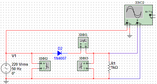
The scheme by which the simulation
The power source simulates a single-phase household network with the following characteristics:
-
sinusoidal current;
-
220 V rms voltage;
-
frequency - 50 Hz.
I did not find an ammeter and voltmeter in the program; multimeters play their role. Later, pay attention to the abundance of their settings, and the ability to choose the type of current.
In the given model, the multimeter XMM1 - measures the current in the load, XMM3 - the voltage at the output of the rectifier, XMM2 - the voltage at the input, XSC2 - the oscilloscope. Pay attention to the signatures of the elements - this will exclude questions when analyzing the drawings, which will be below. By the way, Multisim presents models of real diodes, I chose the most common 1n4007.
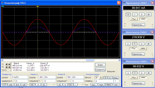
The waveform at the input (channel A) in the field with the measurement results is shown in red. In blue - output voltage (channel B). For the first channel, the vertical division price of one cell is 200 V / div, and for the second channel it is 500. I deliberately did this to separate the waveforms visually otherwise they merged.The yellow vertical line in the left third of the screen is a meter, the voltage value at a point with maximum amplitude is described below the black screen.
The input amplitude is 311.128 V, as was said at the beginning of the article, and the output amplitude is 310.281, a difference of almost one volt is due to a drop on the diode. On the right side of the image are multimeter measurement results. The names of the windows correspond to the names of the XMM multimeters in the circuit.
From the diagram we see that really only one half-wave of voltage is supplied to the load, and its average value is 98 V, which is more than two less than the input current 220 V AC in sign.
In the following diagram, we added a filtering capacitor and one multimeter to measure the load current, remember their signatures so as not to get confused when studying the drawings.
The resistor in front of the diode is needed to measure the charge current of the capacitor to find out the current - divide the number of volts by 1 (resistance). However, in the future we will notice that at high currents a significant voltage drops across the resistor, which can be confusing during measurements, in real conditions - this would cause the resistor to heat up and loss of efficiency.
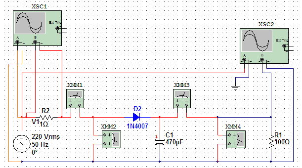
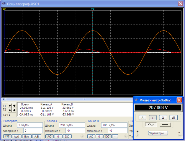
The waveform shows the input voltage in orange and the input current in red. By the way, a current shift is noticeable in the direction of voltage advance.
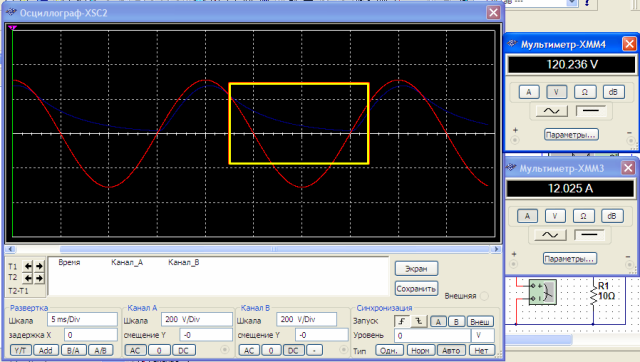
On the waveform of the output signal, we see how it works capacitor - the voltage in the load while the diode is closed and one half-wave passes, decreases smoothly, its average value rises, and the ripple decreases. After, at a positive half-wave, the capacitor recharges and the process repeats.
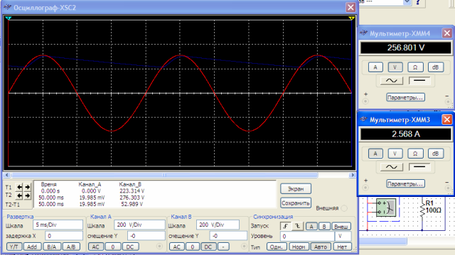
By increasing the load resistance by a factor of 10, we reduced the current, the capacitor did not have time to discharge, the ripples became much less, so we proved the theoretical information described in the previous section about ripples and the effect of current and capacity on them. In order to show this, we could change the capacitance of the capacitor.
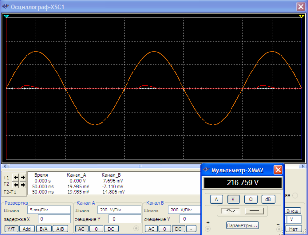
The input signal also changed - the charge currents decreased, and their shape remained the same.
Half-wave circuit
Let's look at how the rectification scheme of both half-periods looks in action. We installed a diode bridge at the entrance.
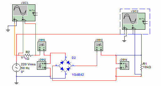
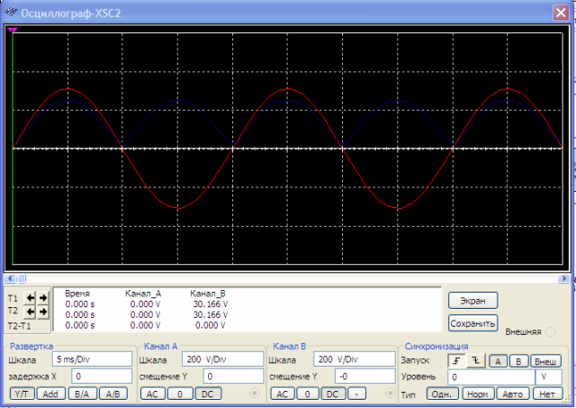
The oscillograms show that both half-waves enter the load, but the ripples are very large.
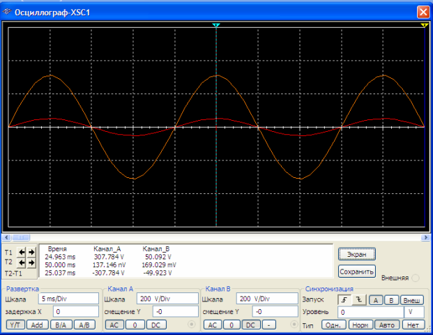
The lower half of the half-wave at the current (in red) appeared on the input waveform.
Reduce ripple by installing a filtering electrolytic capacitor at the input. In practice, it is desirable to install a ceramic one in parallel with it in order to reduce the high-frequency components of the sinusoid (harmonics).
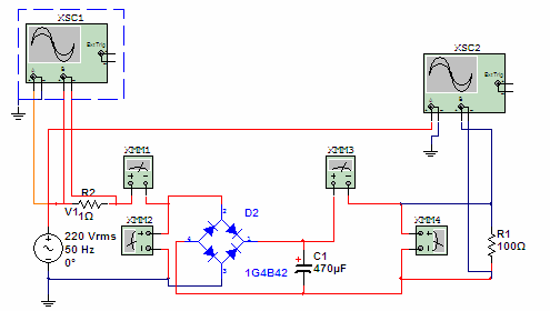
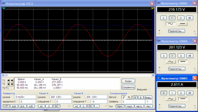
The input waveform shows that the inverse half-wave was added when the capacitor was charged (it becomes positive after the bridge).
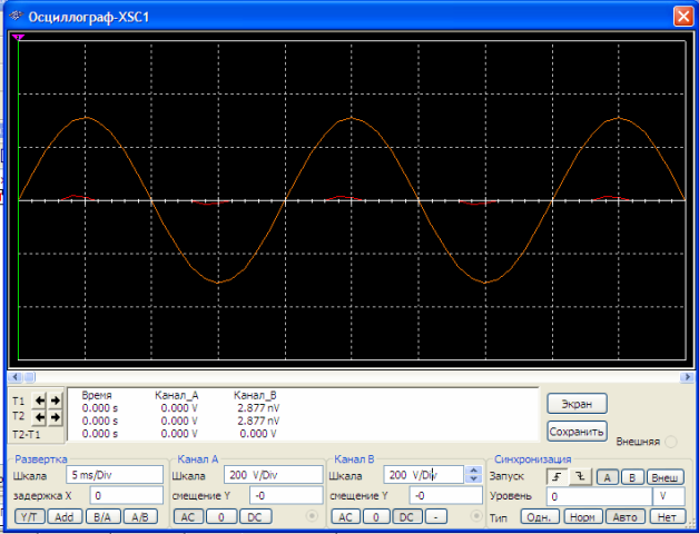
The output waveform shows that the ripple became less than in the first circuit with a filtering capacitor, note that the voltage tends to the amplitude, the less the ripple, the closer its average value to the amplitude.
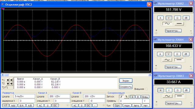
If we increase the load current by 20 times, reducing its resistance, we will see strong ripples at the output.
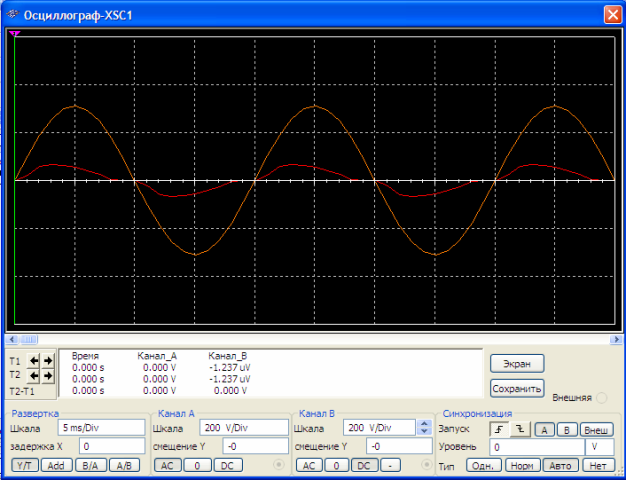
And larger currents of charges at the input, the phase current shift is very noticeable. The process of charging the capacitor does not occur linearly, but exponentially, so we see that the voltage rises and the current drops.
Conclusion
Rectifiers are widely used in all areas of electronics and electricity in general. Rectifier circuits are installed everywhere - from miniature power supplies and radios to power circuits of the most powerful DC motors in crane equipment.
Simulation perfectly helps to understand the processes occurring in the circuits and to study how the currents change as the circuit parameters change. The development of modern technologies allows the study of complex electrical processes without expensive equipment such as spectral analyzers, frequency meters, oscilloscopes, recorders and ultra-precise voltammeters. It avoids errors when designing circuits before assembly.
See also at bgv.electricianexp.com
:
