Categories: Practical Electronics, Interesting electrical news, Home automation
Number of views: 108781
Comments on the article: 3
Automatic lighting switches with infrared and acoustic sensors
 The modern elemental base of electronics allows you to create devices simple in circuitry, but having a fairly wide range of functions. Previously, such devices were only available for use in complex and expensive professional systems, and now their use makes our everyday life more comfortable and easier.
This article will talk about appliances using infrared sensors. Once such sensors were mainly used in security systems, now no one is surprised by the doors that open in front of each incoming person or the automatic inclusion of lighting in the entrance. And all this infrared sensors! Often they are called pyroelectric sensors.
Pyroelectric sensor. Device and principle of operation
Pyroelectric sensors are passive in principle. This means that they do not generate any electromagnetic signals, but simply are infrared receiverTherefore, for humans it is absolutely harmless.
Each item is infrared source, and the human body in this sense is also no exception. Pyroelectric sensors are designed in such a way that they do not respond to infrared radiation itself, its absolute value, but rather to its change. Therefore, even a slight movement of an object, for example, a person will be detected by such a sensor.
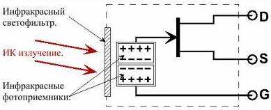
As an example, consider the pyroelectric sensor IRA-E710 from Murata. Its device is shown in Figure 1.
Figure 1. IRA-E710 pyroelectric sensor device
The basis of the pyroelectric sensor is an infrared sensitive photocell that produces an electrical signal proportional to the amount of radiation. To match the photocell with the circuit and the initial signal amplification, a field-effect transistor is used.
If the sensor is built on only one photocell, then it will trigger not only from moving objects, but also simply from external temperature, sunlight, from radiators and temperature changes of the sensor itself, or rather its body.
In other words, the noise immunity of such a sensor is too low. To increase it, pyroelectric sensors are made on the basis of two photocells included in the opposite direction, as shown in the figure, which allows you to compensate for the factors just mentioned.
Such a sensor only responds to changes in the magnitude of the radiation, which allows it to be used as a motion detector. An even greater reliability in the operation of the sensor is provided by a light filter tuned to a wavelength of 5-14 microns. Such radiation is most characteristic of the human body.
However, one should not think that the sensor picks up only the movement of heated objects. There is always a certain infrared background in the room, so moving any object, even with the ambient temperature, causes a change in the general background and the sensor triggers.
The disadvantages of the described sensor can be attributed to the fact that it is sensitive only to movements across, that is, from one photocell to another. When moving along the surfaces of both photocells, the signal will not be generated. Therefore, when installing such sensors, they should be oriented accordingly, as will be discussed above.
In order to get rid of such a harmful effect for especially critical cases, they are developed and applied. sensors based on four photocells. True, sensors of this type are more complex and expensive, which also complicates the scheme of their connection and control.
Sensors are available for conventional and surface mount (SMD) mounting. Their appearance is shown in Figure 2.
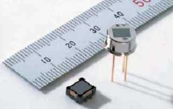
Figure 2. IRA-E710 Sensors. Appearance
The use of motion sensors
Originally motion sensors intended to create burglar alarm systems. With the development of the element base, pyroelectric sensors became much cheaper and more affordable, which allowed them to be used for domestic purposes.
It is above all automatic inclusion of lighting, door opening, as well as management of video surveillance systems. Such automation allows you to save a significant amount of electricity or heat in the room. When used in video surveillance systems, space is saved on the hard drives of the computer that controls the operation of the video system.
The algorithm of the automatic light switch
When the light is turned on automatically, for example, in the entrance, when a person appears in the field of view of the device, the lighting should turn on, and after some time, turn off. While a person is in the field of view of the device, the lighting should not turn off, the shutter speed increases. In daylight, the automatic inclusion of light should not occur.
Spotlights with a motion sensor designed for outdoor installation also work precisely: lighting the gates and the yard near the house, stairs at the entrance to the store and in other cases. Such spotlights are available in conjunction with a motion sensor, or the motion sensor can be separate.
One of automatic lighting control circuits shown in figure 3.
Figure 3. Lighting control scheme from a motion sensor (click on the picture to view the scheme in a larger format)
Description of the circuit
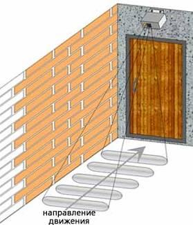
As a receiver of infrared radiation in the circuit used pyroelectric sensor PIR1. In front of its photocells, a modulation lattice of narrow opaque and transparent stripes is installed, which is located horizontally. Therefore, it turns out that for a photodetector, an object moving across the bands of the modulation grating is either open or closed, which causes the appearance of an alternating voltage at the output of the sensor.
The foregoing is illustrated in Figure 4, which shows the correct location of the sensor. The size of the object detected by the device is determined by the bandwidth of the modulation grating. By changing the bandwidth, you can adjust the sensitivity of the device as a whole. The width of the range of the device can be adjusted by changing the size of the window modulation lattice.
Figure 4. Motion sensor installation diagram
The power of the internal amplifier of the PIR1 sensor is supplied to its output 1 through the filter R1C1. The output signal of the sensor is removed from pin 2 and fed to the non-inverting input of the operational amplifier 1 of the DA1 type LM324 chip. This chip is four operational amplifiers (op amps) independent of each other. The only thing that unites them is the common power conclusions and the case.
An amplifier with a gain of about 150 is assembled at OS1, to which the PIR1 sensor is directly connected. If there is no movement in the sensor coverage area, then at the output of ОУ1 there is a constant voltage level, about half of the voltage of the power source.
When a moving object is detected in the field of view of the sensor at terminal 2, an alternating voltage appears, which is amplified by OS1. At the output of OS1, a variable component appears, which is fed through a capacitor C2 to the next amplification stage performed on OS2 with a gain of approximately 100.
After these stages, the signal amplified to the required level arrives to the input of the comparator on OU3 - pin 10 of the DA1 chip. The response level of the comparator is determined by the value of the resistors R8, R11, R20. In the initial state, the output voltage of the comparator is low.
If at the output of ОУ2 - output 14 - rectangular pulses appear that exceed the specified level of operation, at the output of the comparator ОУ3 - output 8 - a high voltage level appears, more precisely, also pulses that charge the capacitor C7. The VD5 diode prevents the discharge of this capacitor through the output of the comparator when it is low. Therefore, the capacitor can only be discharged through the serial circuit R14 and R22. Using a variable resistor R22, the discharge time can be set within 5 seconds ... 5min.
The voltage accumulated on the capacitor C7 is supplied to the non-inverting input of the second comparator made on the OS4, the response level of which is set by the divider R9, R13. The output signal of this comparator is fed to the base of transistor VT1, which, using triac VD2 connects the load.
The response time of the comparator on the OS4 is determined by the charge time of the capacitor C7, which increases by the response time of the sensor: until the movement in the field of view of the device has stopped, the capacitor C7 will recharge. Thus, while someone is moving in the room, the lighting is not guaranteed to turn off.
In order for the lighting to not turn on during daylight hours, the device contains a light sensor made on a VD7 photodiode of type FD263, which is turned on in the opposite direction. Modes of operation are set by the divider R15, R23.
The voltage from the engine of the variable resistor R23 is supplied to the base of the transistor VT2. While the dark photodiode is closed in the room and the voltage at the base of the transistor VT2 is high, therefore it is closed and does not affect the operation of the circuit.
With increasing illumination, the photodiode opens, and the voltage at the base of VT2 drops, which leads to its opening. An open transistor through a VD9 diode shunts the signal from the output of the op amp 2 to the input of the comparator on the op amp 3. Therefore, the capacitor C7 does not charge and the lighting will not be turned on either.
In order to prevent the daylight sensor from turning on the light that the day has come, its operation is blocked through the VD8 diode connected to the output of the comparator on OU4. Capacitor C10 provides a delay in turning on the ambient light sensor when the lamp is turned on, thereby preventing false alarms of the sensor.
The power of the device is transformerless. Through the quenching capacitor C9, the mains voltage is supplied to a rectifier made on diodes VD4 and VD6. The ripple of the rectified voltage is smoothed by the capacitor C8, and the voltage is stabilized at 16V by the Zener diode VD3. This voltage is used to power the key stage on the transistor VT1, which controls the operation of the power switch on the triac VD2.
A 9.1V parametric voltage regulator is assembled on the elements R2, C3, and VD1, which is used to power all nodes of the device: a PIR sensor, DA1 microcircuit, and daylight photo sensor on the transistor VT2.
The described circuit is produced as a kit by Master Kit. The kit contains all the necessary radio components, a finished circuit board and a housing for assembling the device, shown in Figure 5. The kit also includes instructions for assembling and setting up the device.
Although in general the circuit is considered to be simple, and with error-free assembly from serviceable parts, it should start working immediately, I want to draw attention to the fact that it has transformerless power. Therefore, during assembly and commissioning, you should be extremely careful, comply with safety regulations, and even better, use an isolation transformer.
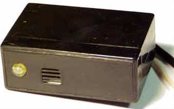
Figure 5. Case from the Master Kit kit
The circuit fully enters the operating mode in one and a half to two minutes after switching on, therefore all settings should be made after this time has passed. The settings are simple and are reduced to setting the required delay time by the resistor R22, and with the help of the resistor R23 the threshold of the light sensor is selected.
The threshold of the motion sensor itself is determined by the value of the resistor R11.If an increase in sensitivity is necessary, its value can be somewhat reduced. Accordingly, with a large number of false positives, you will have to change the value in the direction of increase.
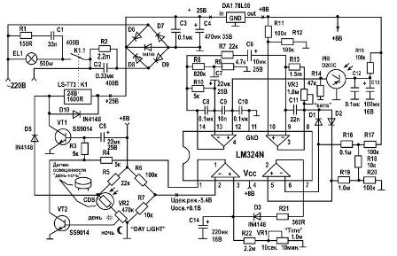
Figure 6 shows another diagram of an infrared motion sensor, which is very similar to the circuit shown in Figure 3.
Figure 6. Infrared motion sensor. Option 2 (click on the picture to enlarge)
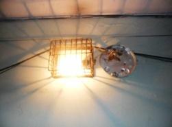
A similar scheme is equipped with a searchlight with a halogen lamp in the form of a single device, and is installed, as a rule, at the entrances of private households. Its purpose is to turn on the light in the yard when the owners of the house arrive, and in addition to warn the owners about the penetration of guests, including uninvited ones, into the territory. The scheme itself is very similar to the previous one and performs the same functions, so a detailed description is not required. Let us dwell only on individual nodes.
As an infrared sensor, a PIR D203C phototransistor is used, the signal from which is fed to the DA1 chip, the same as in the previous circuit. The sensitivity of the sensor is adjusted by a variable resistor VR3. The light sensor is made on a CDS photoresistor, which, through daylight transistor VT2, blocks the operation of transistor VT1, which includes a load control relay. Therefore, in the daytime, the inclusion of the searchlight does not occur.
Like the previous one, the circuit contains a time delay, which is performed on the capacitor C14, the discharge time of which is regulated by a variable resistor VR1. The time adjustment limits are indicated directly on the diagram.
A halogen spotlight with a motion sensor is designed for installation on the street, so cats, dogs or other small animals can fall into the sensor coverage area, in addition to people. This can cause false triggering of the sensors and the inclusion of light.
To protect against such false alarms, it is recommended to install a protective screen in front of the sensor, which will somewhat limit the visibility range of the device from below: it is quite enough to see not the entire gate, but only its upper half, to distinguish the person who has come.
In more complex motion sensors, this problem is solved by integrated microcontroller, which is quite capable of determining the size of an object: a machine, a person, or a mouse. Of course, such sensors are more expensive.
Automatic lighting switches with acoustic sensors
For light control in the entrances of apartment buildings are also used optical acoustic switches. The switches contain a microphone, an optical sensor, and an output key device.
The logic of the operation of such switches is the same as that of infrared: in the daytime, the microphone is turned off by an optical sensor, and in the dark the lighting will turn on even with insignificant sounds in the entrance. The exposure time is about 1 minute, after which the light goes out.
With the new occurrence of sounds, the cycle repeats. The microphone sensitivity is such that it picks up sound at a distance of up to 5 m, which is quite enough for access conditions. Of course, such a sensor cannot be used on the street, because the light will turn on from any sound, for example, from a car passing by.
Structurally, optical-acoustic switches are available in two versions: either as a separate unit mounted on a wall or ceiling, or built-in to luminaires of various designs. Such switches are shown in figures 7 and 8, respectively.
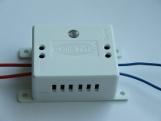
Figure 7. Optical-acoustic energy-saving switch EV-05
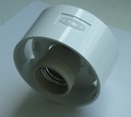
Figure 8. The EVS-01 lamp with a built-in optical-acoustic switch
The price of such switches, as a rule, is less than the switches with an infrared sensor, so they can be recommended for use in housing and communal services, although this does not exclude the installation of infrared sensors.
Read also:How to choose, configure and connect a photo relay for outdoor or indoor lighting
See also at i.electricianexp.com
:

