Categories: Interesting electrical news, Electrician at home
Number of views: 226017
Comments on the article: 12
Lighting Control Schemes
The article provides lighting control circuits using walk-through and cross switches, bistable relays, dimmers, dimmers, photorelay, timers and infrared motion sensors.
Lighting control schemes have already been repeatedly considered in the literature and on the pages of various Internet sites of electrical orientation. Therefore, here we will try to outline the various existing solutions.
The simplest control schemes for a one- or two-key switch are known to everyone and, therefore, few people are interested, so we will go straight to the discussion multi-spot lighting control circuits.
Let's start with a specific simple situation - let's say you have two floors in a country house. In the evening you climb the stairs to the second floor. Naturally, you need to turn on the lights on the stairs. Turn on on the ground floor. We rise to the second floor. Now the lights on the stairs need to be turned off.
And how to do this if the switch is installed on the ground floor? Naturally, the obvious answer is that the control of lamps should be carried out from two places - from the first and second floors.
At first glance, nothing complicated - it’s enough to install a switch on each floor, which are connected in parallel and control them independently of each other. But such a scheme will not work according to the algorithm we need - with its help, you can turn on the light from any of the two switches, but turn it off - only from the one from which it was turned on - because one switch in the on state will block the operation of the other. Therefore, for the considered situation with the ladder, this scheme is absolutely unacceptable.
To implement lighting control from two places are necessary special switches called pass-through. In general, in this situation, the term “switch” is incorrect. This is a "switch" because It has three contacts - one movable and two motionless. Depending on the position of the switch key, the movable contact closes with either one or the other fixed contact. But in order not to get confused in terms, we will call this switch a passage switch.
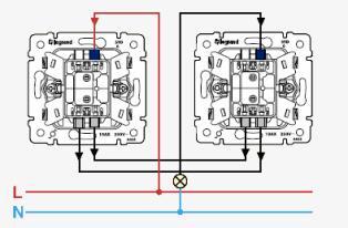
By turning on two such switches according to the scheme shown in Figure 1, we will be able to control one lamp (or several at the same time, if they are connected in parallel) from two points independently of each other. The moving (switching) contact in this diagram is the contacts highlighted in blue.
Fig. 1. Control of one lamp from two points.
A special feature of the passage switches is that they do not have a strict key position. If in a conventional switch, as a rule, the on position is pressing up and turning off down, then in the through switch, the on-off position will depend on the position of the second switch. If we assume that you turned on the light from the first switch, “clicking” it up, and turned off from the second, then the next time you turn on the light with the first switch, you need to “click” down.
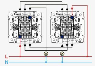
In addition to single, there are dual breakers. They allow two independent luminaires to be controlled from two places. These are actually two single pass-through switches in one enclosure. The connection diagram of such switches is shown in Figure 2.
Fig. 2. Control of two lamps from two points.
But sometimes a situation requires management not from two, but from three or more places. There are already no walk-through switches to do. The circuit must be supplemented with four-contact switches - the so-called cross switches.
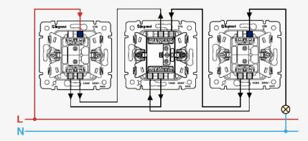
The cross switch has four contacts and a more complex design, as compared to the passage switch. It is installed “in the middle” of the circuit — that is, the first and last switches in the lighting circuit will be walk-through, and cross switches must be installed at all “intermediate” points. As an example, Figure 3 shows a three-point luminaire control circuit.
Fig. 3. Three-point lamp control.
The control circuit with passage and cross switches is not the best solution when you need to control lighting from three or more places. Such a control scheme is much easier to organize with the help of bi-stable ones, or as they are called differently, bistable relays.
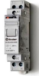
This relay is an electronic circuit of a trigger - a device with two stable states and is controlled by a short-term pulse supplied to its input. This allows the use of non-latching switches (buttons) for lighting control. All buttons are switched on in parallel to each other, which can greatly simplify the circuit and, accordingly, the installation of lighting. Typically, such a relay is a standard 17.5 mm module mounted on a DIN rail and mounted in a control cabinet (Figure 4)
Fig. 4. Appearance of a bistable relay.
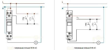
The bi-stable relay shown as an example, depending on the modification, may have one normally open contact, two normally open contacts, or a normally open and normally closed contact. Such relays can operate both in a 230V network and at a voltage of 24V. The bi-stable relay switching circuits are shown in Figure 5.
Fig. 5. Schemes of inclusion of a bistable relay.
To implement a lighting control circuit on a bi-stable relay, it is most convenient to use its normally open contact. In both circuits shown, such a contact is a contact having outputs 1-2. The number of control buttons can be any, and they are all included in parallel.
The first press of any button will give a control voltage level to input A1, which will cause the relay to turn on, close the contact and, accordingly, turn on the light, the second press will turn off and so on in a circle.
The advantage of this circuit from the above circuit on the passage switches is the lack of the need for cross switches and a much simpler installation of the lighting system. The disadvantage is the use of a special bi-stable relay. But with such a relay, this circuit is most optimal both in terms of installation and subsequent troubleshooting.
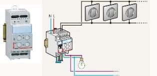
Separately, it is necessary to dwell on devices such as dimmers (dimmers). They allow you to control the brightness of the lamp. There are regulators for various types of luminaires - with incandescent lamps, with fluorescent lamps, halogen lamps, etc. For example, we give the appearance and circuit of the remote control from different points dimmer for incandescent lamps (figure 6).
As can be seen from the diagram, the control buttons in this dimmer are turned on similarly to the control circuit by means of a bi-stable relay - they are all connected in parallel and there can be any number of them. To ensure protection, the dimmer is switched on via a circuit breaker. The total power of the lamps can be 600 watts. The switching circuit for fluorescent lamps is similar, the only difference is that a different type of regulator is used.
Fig. 6. Remote control dimmer switching circuit.
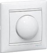
This type of dimmer is mounted in a control cabinet on a DIN rail. However, in most cases, in everyday life they use dimmers that are installed instead of existing switches. They have landing dimensions, like a standard switch. The appearance of the dimmer is shown in Figure 7.
Adjustment is carried out by turning the knob of the potentiometer - when rotating clockwise, the brightness of the lamp increases, counterclockwise - decreases. Sometimes control is done using buttons. The power regulating element in the dimmer circuit is triac (triac).
Fig. 7. Dimmer.
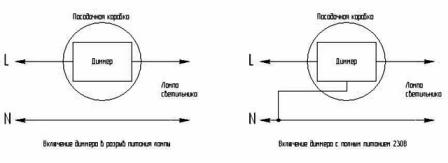
When replacing conventional switches with dimmers, one should not forget one very important nuance - there are dimmers that are included in the luminaire's power supply, and some require a constant 230V power supply.
In the first case, no replacement questions arise - the dimmer just turns on instead of the switch. In the second case, it is necessary to bring an additional neutral wire into the landing box - to ensure full power supply of 230V. Therefore, if the wiring is not reconstructed, the first method is clearly preferable. The wiring diagrams of various types of dimmers are shown in Figure 8.
Fig. 8. The inclusion of various types of dimmers.
The lighting control methods discussed above, with all their convenience, have one point, and maybe for someone a drawback - to turn the lighting on or off, you need to go to the switch. Not to be attached to the switch and at the same time to adjust brightness allow electronic remote switches. They come both with infrared (IR) control, where a remote control from any household appliances is used as a control panel, and with radio control.
As an example of an IR-controlled switch, we can name the well-known Sapphire switch (Figure 9). It allows you to both turn on / off the light, and smoothly adjust the brightness of the lamp. For all its advantages, it should be noted as a drawback that this switch can be controlled only within the line of sight, how long the "range" of the control panel will last - usually no more than eight meters.
Fig. 9. Appearance of the Sapphire switch.
Switches operating on the radio channel are devoid of such a drawback as control only within the line of sight. The radio signal can also pass through various obstacles - walls, floors, etc. To a certain extent, of course. In these switches, as a rule, the frequency of 433 or 492 MHz is used, which does not require permission from the radionuclide authorities. The output power of the transmitters for such devices is not more than 10mW.
Remote-controlled switches (both via IR and radio channels) can be either single-channel (allowing you to control only one load), and multi-channel. Multichannel switches are convenient in that they can be placed, for example, in a control cabinet and to reduce control objects at one point. Single-channel switches are usually placed in the junction boxes of the lighting line.
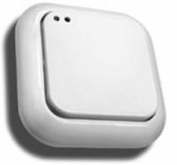
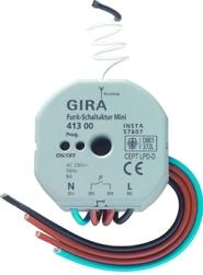
An example of the implementation of a single-channel radio switch mounted in a junction box is shown in Figure 10. Mandatory, both single-channel and multi-channel switches provide local (manual) control in case of failure of the control panel.
Fig. 10. Single channel radio switch.
Radio-controlled switches, although they have a significantly greater radius of action than switches built on infrared rays, however, it is limited - as a rule, no more than 100 meters (although there are different options).
But what to do if you need to turn on lighting or any other load, being tens or hundreds of kilometers from a managed facility? And this is not such a useless function - for example, the remote inclusion of lighting in a country house will create the effect of the presence of the owners, turn on the heating of the underfloor heating in the winter, so that it would be warm at your arrival, turn on the air conditioning in the summer, etc.
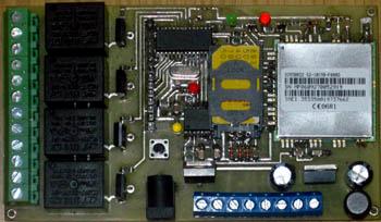
This is where systems that are remotely controlled via cellular lines or over the Internet come to the rescue.Such devices are now quite widely represented on the market. The author of this article at one time also independently developed a four-channel “switch” via GSM. Its appearance is shown in Figure 11.
Fig. 11. Four-channel control and monitoring device.
This device, called the multifunctional control and monitoring device, has a built-in GSM module. To use it, just connect the required loads to the output channels and insert an activated SIM card.
Access to the control is as follows - dialing is done to the number of the installed SIM card, after the programmed number of calls, the device connects to the line and you must enter the password set from the phone keypad. If the password is incorrect, the device is disconnected from the line; if it is correct, you can control (enable or disable) any of the four loads.
This project is non-profit, all documentation about it, including microcontroller firmware, laid out in the public domain and anyone who has certain knowledge in the field of electronics can make it yourself.
All the above control schemes have one common attribute - they are controlled by a human command, in other words, by an operator. But there is a whole class of devices that can work without the direct involvement of a person. These include a control relay on command from a light sensor, a motion sensor, and according to a previously established time algorithm.
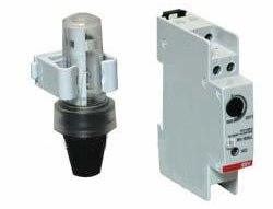
Relay with light sensors (photo relay) often used for street lighting control - when dark, they turn on outdoor lighting fixtures. The threshold of operation of such relays can be adjusted depending on the level of illumination. Appearance photo relay together with the sensor is shown in Figure 12. It contains one control contact, which allows you to control the lamp directly from the relay, or, under heavy loads, through an additional power relay (contactor).
Fig. 12. Photo relay with sensor.
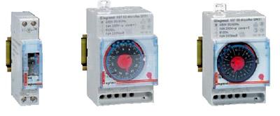
Relays that control the load according to a given time algorithm are called programmable timers. They prescribe the necessary time for switching on and off the load. Sometimes timers integrate with a photo relay.
What is it for? Suppose we need to turn on the outdoor lighting after dark, then turn it off from one in the morning, turn it on again at four in the morning, and turn it off in the morning when it gets light. For this, the photo relay and timer are assembled in a serial circuit. When dark, the photo relay will turn on the lamp, but at one in the morning the timer will break the circuit and the lamp will go out. Then at four in the morning the timer will assemble the circuit again - the lamp will turn on. And finally, when it becomes light, the lamp will turn off the photo relay.
Depending on the modification of the timer, it is possible to program events from one day to one year in it. A variety of such timers are astronomical relays. As a rule, these relays are also used to control outdoor lighting - the geographical coordinates of the area are entered into it as an input value, and the device, on the basis of this information, automatically calculates when it is necessary to turn on or off the lighting. The appearance of some types of timers is shown in Figure 13.
Fig. 13. Appearance of some types of programmable timers.
Finally, let’s focus on lighting control with infrared motion sensors. Similar sensors are used in security systems to record the presence of a person in a protected area. Only there the sensors are designed so that when they are triggered, the security system sends an alarm signal to the remote security department.
In our case, the operation of the sensor should turn on the lighting for a certain time. If after this time no activity (movement) is observed in the controlled area, the lighting turns off.Otherwise, the lighting remains on for the same time interval.
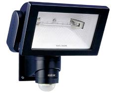
The use of lamps controlled by motion sensors is very convenient in common areas - on stairwells and corridors of apartment buildings. Such lamps are also excellent for outdoor lighting, for example, in the courtyard of a house. They allow not only conveniently controlling lighting, but also saving energy, which is quite relevant in our time. The appearance of the luminaire with an integrated IR sensor is shown in Figure 14.
Fig. 14. Appearance of the lamp with an infrared sensor.
Of course, in one small article it is impossible to cover all existing modern lighting control methods. In it, I tried to consider the most traditional and often used.
See also:Schematic and wiring diagrams of lighting in an apartment and a house
Mikhail Tikhonchuk
See also at bgv.electricianexp.com
:

