Categories: Practical Electronics, Microcontroller circuits
Number of views: 83599
Comments on the article: 6
How to make a powerful New Year garland with Chinese brains
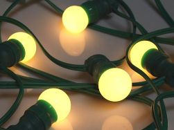 The New Year is coming soon! On the shelves of stores next to tangerines, sweets and champagne, Christmas toys appear: colorful balls, tinsel, all kinds of flags, beads and, of course, electric garlands.
Perhaps the usual garland of multi-colored light bulbs cannot be bought. But various flashing lights, mainly of Chinese manufacture, simply can not be counted. Microscopic bulbs can be placed on a piece of cardboard or woven into a carpet of wires, which can decorate an entire window immediately.
Christmas tree garlands are also very diverse, especially the external design, design. The cost of such garlands is small, as, in fact, the power of the bulbs.
Most garlands have a small plastic box with one button, a cord with a power plug and wires going to a garland of colorful lights. Garland decoration can be the most diverse.
The simplest and cheapest option consists of microscopic bulbs inserted in heat shrink tube. On the back of the packaging box is written instructions for replacing bulbs and safety precautions, although no spare bulbs are included. It is these garlands that are sold in the All 38 chain of stores, however, recently, forty rubles each.
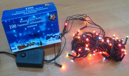
Figure 1. A garland for forty rubles
Garlands of a different style have small plastic plafonds on bulbs, for example, in the form of transparent flowers with petals. But the box with the button remains the same, although the price of a garland reaches two hundred rubles. Let's try to open the box, and see what is inside.
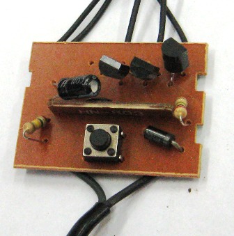
Figure 2. Appearance of a garland controller with three thyristors
At the bottom of the figure, two wires are shown, this is just connecting the device to the network. There is also a button with which the operating modes are switched. In the upper part, you can see three thyristors and wires extending to the garlands.
In the middle of the board is microcontroller in a chip, - such a black drop mounted on a small printed circuit board. The board has pads with which the controller is soldered into the main board.
How many thyristors are on the board
To the outputs of the microcontroller are connected the control electrodes of the thyristors, which include a garland of bulbs. The microcontroller has four outputs, but often, instead of four thyristors, only three are installed on the board, and in some cases only two.
The necessary visual effect is achieved by connecting the garlands and the arrangement of the bulbs: in one garland, the bulbs of two, or even three colors are sealed. Just such a board is shown in Figure 2.
If you look at this board from the printed circuit side, you can see that the three thyristors are soldered, and under the fourth there are holes with tinned contact pads, as shown in Figure 3. In some cases, the holes are not even drilled, they say, whoever pleases, they will drill .
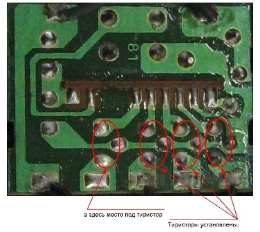
Figure 3. Garland controller board. Free space for thyristor
Here we should note such a feature: if the controller output is not connected anywhere, this does not mean that it is inoperative. The program in all controllers is flashed, apparently the same, all controller outputs are involved.
This can be easily verified with the arrow tester. If you measure the constant tension on your free leg, then the arrow will jump, twitch and deviate along with the blinking of other garlands. It is enough to simply solder the missing thyristor into the board, and, please, we get a full four-channel garland.
The thyristor can be taken from an old faulty board (it happens that the controller becomes unusable) or buy an additional garland for forty rubles and remove the thyristor from there. For a good cause, the costs are extremely small!
Schematic diagram of the garland
On a printed circuit board, it is easy to make a circuit diagram. There are two types of circuits, slightly different from each other. The first, most perfect option is shown in Figure 4.
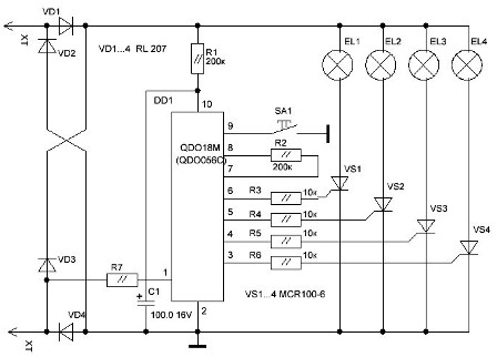
Figure 4. The controller of the Chinese garland. Option 1
The entire circuit is powered through diode bridge VD1 ... VD4. The garlands are powered by a pulsating voltage and are switched on by the controller through the thyristors VS1 ... VS4. Resistor R1 and microcontroller DD1 form a voltage divider, the output of which produces a voltage of 12V.
Capacitor C1 smoothes the ripple of the rectified voltage. Through the resistor R7, the mains voltage is supplied to the input of the controller 1 to synchronize the circuit with a frequency of 220V, which allows phase control of the thyristors. This synchronization allows for smooth ignition and fading of garlands. It is these boards that can be found in expensive garlands.
The board shown in Figure 3 is assembled according to a somewhat simplified scheme, which is shown in Figure 5.
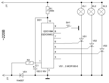
Figure 5. The controller of the Chinese garland. Option 2
It is immediately evident that there are only three thyristors, and only one diode remains from the rectifier bridge. Resistors from the control electrodes of the thyristors also disappeared. But, in general, consumer properties remained the same as in the previous circuit, despite the fact that the bulbs are lit only when there is a positive half-period of the mains voltage on the upper wire of the circuit. Without a rectifier bridge, half-wave rectification is obtained.
This version of the circuitry solution is inherent in those garlands that are "all in forty." That, in fact, is all that can be said about the circuitry of Chinese Christmas garlands.
How to connect powerful lamps
The power of the garlands is small, the bulbs are simply microscopic, except for a home Christmas tree, they are unlikely to fit anywhere else. But sometimes you need to connect a garland with powerful incandescent lamps, for example, for decorative illumination of building facades. Such a refinement has already been given in the article. "How are the New Year garlands". The scheme of the modified garland is shown in Figure 8 in the mentioned article.
The drawback of the circuit can be considered the need for an additional 12V power supply, as well as the alteration of the controller board itself: it is proposed to replace the thyristors with KT3102 transistors.
If you do not want to redo the board
It is much easier to do without reworking the controller board. All you have to do is make four powerful output keys with optocoupler junctions and attach them instead of low-power garlands. The power key diagram is shown in Figure 6.
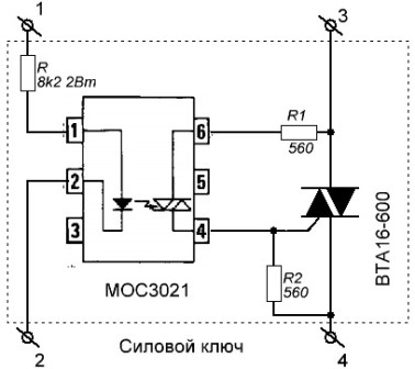
Figure 6. Powerful opto-coupled power switch
Actually, the typical scheme works flawlessly, it does not contain any pitfalls. As soon as the LED of the MOC3021 optocoupler is illuminated, a low-power optocoupler thyristor is opened and the control electrode and the anode of the BTA16-600 triac are connected through pins 4, 6 and resistor R1. The triac opens and turns on the load, in this case a garland.
The optocoupler should be used without the built-in CrossZero circuit (detector of the line voltage transition through zero), for example, MOC3020, MOC3021, MOC3022, MOC3023. If the optocoupler has a CrossZero node, then the circuit WILL NOT WORK! This should not be forgotten.
Triac BTA16-600 has the following parameters: forward current 16A, reverse voltage 600V. At a current of 5A and a voltage of 220V, the load power is already a whole kilowatt. True, you need to install a triac on the radiator.
The metal substrate is isolated from the crystal, as indicated by the letter A in the marking of the triac. This makes it possible to install triacs on the radiator without mica gaskets and screw insulators.By the way, it is these triacs that are in the power regulators of household vacuum cleaners, while the radiator is blown by the air stream at the outlet of the vacuum cleaner.
If the load power is not more than 400W, then you can do without a radiator. The triac pinout is shown in Figure 7.
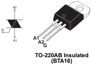
Figure 7. BTA16-600 Triac Pinout
This figure will not be superfluous when assembling the power key circuit. All four power keys are best assembled on a common circuit board. It is better to assemble the R resistor from two resistors with a power of 2 W each, which will avoid their excessive heating. The maximum current of the input LED of the optocoupler is 50 mA, so a current of 20 ... 30 mA will ensure its long-term trouble-free operation.
So, we will assume that the power switches are made, it remains only to connect them according to the circuit shown in Figure 8.
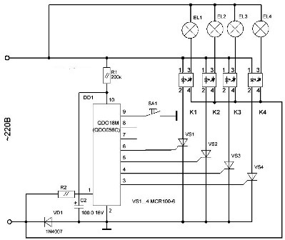
Figure 8. Connecting power keys to the controller board
In general, everything is clear and simple. Garlands are soldered from the controller, and the input circuits of power keys are soldered instead. In this case, no intervention is required in the printed wiring of the controller. The exception is soldering an additional thyristor, provided that it can be found. You will also have to slightly power up the power cord with the plug, since the original one has a very small cross section.
With proper installation and serviceable parts, the circuit does not need to be configured. The design of the device is arbitrary, best of all in a metal case, of suitable sizes, which will act as a radiator for triacs.
In order to ensure electrical safety, the device should be turned on through a circuit breaker, or at least a fuse.
Boris Aladyshkin
See also at i.electricianexp.com
:

