Categories: Practical Electronics, How does it work
Number of views: 316195
Comments on the article: 20
How are the Christmas lights
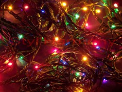 New Year holidays come as always unexpectedly and bring with them a lot of pleasant trouble. It’s time to think about gifts, first of all for children, for adults to set the table, pick up good music and be sure to put a Christmas tree, which to dress up, so that the guests would have fun and cozy. And the first thing to hang on the tree is, of course, Christmas tree garlands. All other toys, as a rule, are hung after garlands. Next, we will talk about the device of a variety of different Christmas garlands - old and modern.
In ancient times, when there was no electricity, and the New Year was already celebrated, special New Year candles were lit on the Christmas tree. This decoration was very fire hazard. But these times have already passed, everyone began to use electric garlands.
These were ordinary small bulbs from a flashlight or from the backlight of a scale in a radio receiver, connected in series. Of these bulbs, garlands were made by enthusiasts mainly with their own hands. They just picked up a soldering iron, who, of course, knew how to use it, took a wire and bulbs, and after a while the New Year's garland was already hanging on the tree.
A little later, New Year's garlands began to be produced industrially. Small-sized lampholders for lamps and colored shades of various shapes were used. Sometimes shades were made transparent, and the lamps themselves were painted.

Flashing lights and blinkers
But calmly looking at the glowing Christmas garland is somehow unhappy, I want my soul to turn around. Apparently, this is facilitated by some kind of blinking of the garland. In general, a blinking garland attracts with its beauty, and even the expectation of some kind of miracle or surprise. If there are several garlands, then it is possible to get various lighting effects, for example, running fire, running shadow, running twos and triples, as well as many other interesting effects.
Once such designs were developed by radio amateurs, these circuits were published in amateur radio magazines, as a rule, in November issues. But these magazines, under the conditions of socialist mismanagement, arrived late almost for a whole month, so by the New Year only last year's flasher could be made.
As an element base, microcircuits of a small degree of integration were used, primarily K155 and K561 and their varieties. As examples, we can cite the scheme from the journal "Radio" No. 11 of 2002.
In this magazine, the author I. Potachin published several schemes for managing garlands at once. The most interesting scheme is called "Musical garlands."
The basis of the circuit is a counter DD2 type K561IE16, which through the keys on the chip DD3 and transistors VT4 ... VT7 controls four LED garlands. The most interesting thing is that the UMS8-01 musical synthesizer chip is used as the master oscillator. Such microcircuits were used once for voicing children's toys and musical calls: they simply played the melodies recorded in them.
So in this circuit, the output sound signal is also used to clock the counter. One can only guess how the pictures generated by the LEDs against the background of this sound will look. Naturally, music also sounds through the speaker.
Further in the same magazine, in the same article, several more circuits of the same author were published, but already using flashing LEDs. Here are the calculations of LED garlands.
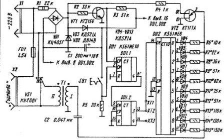
In the journal "Radio" No. 11 of 1995, a scheme was published under the name "Automatic control unit for garland" by A. Chumakov. The circuit provides alternating smooth ignition and damping of the garland at a speed specified by the control unit. The device diagram is shown in Figure 1.
Figure 1. Scheme of the automatic control unit for garland
If you look closely, the circuit represents a triac power regulator made on a KT117A double-base transistor. Only the charge rate of the capacitor does not change manually using a variable resistor, but by switching individual resistors using a counter - a K561IE8 decoder. For comparison, Figure 2 shows a diagram of a phase power regulator using a KT117 two-base transistor.

Figure 2Power Phase Circuit Diagram
Microcontroller management of a New Year's garland
As structures on microcontrollers appeared in amateur radio creativity, Christmas flashers, or as they are respectfully called “lighting effects automatons”, also began to be developed on microcontrollers. The most exotic design was published in the journal Radio, No. 11, 2012, p. 37, entitled “Cell Phone Drives a Christmas Garland,” by A. Pakhomov.
The basis of the design was taken by a board from a faulty Chinese garland. The author writes that he was attracted by the originality of the output stage, controlled directly from MK. He recalls those flashing lights that were built on K155 series microcircuits, powerful KU202 thyristors (there simply weren’t others), and as a whole, you could put a Christmas tree on such a flasher.
And here it was enough to change the controller on the faulty board, write a program with lighting effects and supplement it with some control panel. This remote control was the old Siemens C60 phone lying around idle. The microcontroller AT89C51 was used as the manager. What came of this is shown in Figure 3.
Figure 3. Microcontroller control scheme for the New Year garland (click on the picture to enlarge)
Although this controller is already outdated and discontinued, it is one of the best developments of Intel, later released by Atmel. Designs on this MK never hang, they do not need a watchdog. The command system is so good that it still remains unchanged, despite the emergence of new models of the MSC-51 family.
Simple LED flasher
Slightly higher than the article by A. Pakhomov in the same journal "Radio" No. 11, 2012, an article by I. Nechaev "From the details of CFL. LED flasher for a Christmas toy. " The circuit is made on a three-color LED and three symmetrical DB-3 dinistors “extracted” from motherboards from faulty energy saving lamps.
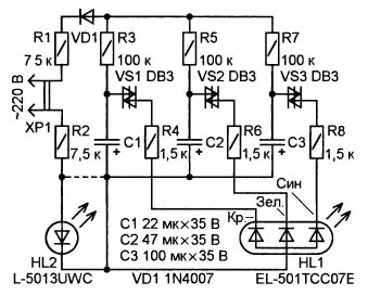
Figure 4. Scheme of a simple LED Christmas garland
Each channel of a three-color LED is controlled by its relaxation generator, assembled on DB-3. Consider the operation of the circuit as an example of one channel, for example, red.
The capacitor C1 is charged through the resistor R3 from the rectifier R1, VD1 to the breakdown voltage of the dynistor VS1 (32V). As soon as the dinistor opens, capacitor C1 is discharged through the red element of the three-color LED, resistor R4, and dinistor VS1. Next, the cycle repeats.
The red, green and blue elements of the three-color LED have their own generators and operate independently of each other. At the same time, the frequency of each generator is different from the other, therefore flashes occur with a different period. The design is placed in a transparent case and can be used, for example, as a Christmas tree top. If you add a white HL2 LED to the circuit, then color flashes will occur on a white background.
Many more descriptions of the designs of domestic amateur radio fans, old or new, good or bad, could be given, but they were all made almost in single copies. Modern stores are completely overwhelmed with electronics made in China. Even New Year's garlands and those are Chinese, besides they are now worthless. Let’s see what is hidden inside.
Controller of chinese new year's garland
Outwardly, everything looks very simple. A small plastic box with one button, which includes a power cord with a plug, and four garlands come out.When you turn on the garland, they immediately begin to show all the lighting effects in turn. There are 8 of these effects, as indicated by the inscriptions under the button. At the touch of a button, you can simply switch directly to the desired light picture.
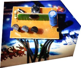
If you open the box, then everything inside is also quite simple, as shown in Figure 5.
Figure 5
Here you can consider all the details. The microcontroller, as always, is made in the form of a drop of a black compound, near it a control button, electrolytic capacitor, a single diode and three output thyristors.
There is a place on the board for the fourth thyristor, and if you solder it, you get another additional channel. In the controller, this channel, as a rule, is also flashed. Just our Chinese friends saved one thyristor. Those who have ever opened such control units assure that only two thyristors are sealed in some boxes. The economy must be economical! Our still Soviet slogan.
Despite such a small size, PCR406 thyristors have a reverse voltage of 400V, and a forward current of 0.8A. If we assume that the load consumes a current of only 25% of the maximum, then at a voltage of 220V, you can switch power 220 * 0.2 = 44 (W).
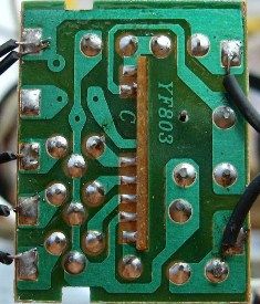
Figure 6 shows a printed wiring, according to which you can sketch a circuit diagram, which has been done repeatedly. Here you can see the holes for the fourth thyristor, just the one that was saved.
Figure 6
Savings also affected the diode bridge: instead of four diodes, only one is used on this board. And everything else corresponds to the circuit shown in Figure 7.
Figure 7
The mains voltage is rectified by the diode bridge VD1 ... VD4 and through the quenching resistor R1 is fed to the 10th output of the microcontroller. To smooth the ripple of the rectified voltage, an electrolytic capacitor C1 is also connected here. The current consumption of the microcontroller is very small, so in the future, instead of a bridge of four diodes, the Chinese decided to do one.
A small remark about increasing the reliability of the entire circuit as a whole. If a Zener diode with a stabilization voltage of 9 ... 12 V is soldered in parallel to capacitor C1, then the likelihood of failure of the microcontroller or simply explosions of the thyristors will decrease much.
The R7 resistor connected to pin 1 of the microcontroller directly from the network wire deserves special attention. This is done to synchronize with the network in order to phase control the power. This is exactly what works when the garland lamps light up or go out.
On the right side of the microcontroller there are thyristor control outputs and a control button, which was described above. Thyristors turn on at the moment when a high level appears at the corresponding output of the MK, then the corresponding garland lights up.
Sometimes New Year's garlands of high power are required, from several hundred watts and above. In this case, the considered circuit can be used as a "brain", it is enough to simply supplement it with powerful triac keys. How to do this is shown in Figure 8.
Figure 8. Schematic of New Year's garland of big power (click on the picture to enlarge)
Here you should pay attention to the fact that the power supply of the MK is carried out from a separate source galvanically isolated from the network.
LED lights
They use the same controller with one button, the same thyristors, but instead of bulbs, garlands are composed of LEDs in three or four colors. Each garland contains at least 20 LEDs with current-limiting resistors.
Moreover, the design of such a garland is just a Chinese mystery: in the first half of the garland, a resistor is soldered to each LED, and the remaining ten pieces are simply connected in series. Again, saving immediately ten resistors.
This design can apparently be explained by production technology. For example, on the one line they collect the first half, which is with resistors, and on the other line without resistors.Then it remains only to connect the two halves into one. But this is only a hunch.
It is hoped that everything is in order with you, at least with New Year's garlands. Therefore, decorate the Christmas tree, cover the festive table, invite guests, celebrate the New Year. Happy New Year, comrades, friends, gentlemen! This is how you like it more.
See also on this topic:Tips for repairing Chinese New Year garlands
Boris Aladyshkin
See also at bgv.electricianexp.com
:

