Categories: Featured Articles » Practical Electronics
Number of views: 95690
Comments on the article: 3
DIY LED Garland Controller
 Description of a simple LED garland control circuit.
Now it’s not a problem to buy a New Year's garland with a controller: there are a sufficient number of Chinese-made flashing lights on sale.
It would seem that he went, bought everything. But it will be much more pleasant if the garland is created with your own hands. It will help revive the old garlands inherited from grandparents along with old Christmas-tree decorations.
Such a control device (controller, automatic lighting effects) is not at all difficult to assemble. Enough make circuit board and solder a few details into it.
There are three areas in the development of lighting effects control devices: microcontroller systems, systems with the use of RPZU, and control devices on logic microcircuits of a small degree of integration.
There is no doubt that the first two systems have the greatest number of effects, and microcontroller systems are even simpler in circuit design (just a microcontroller and output keys), but such devices will require a program to be written. In addition, you also need a programmer that runs on a computer. Therefore, the controller on logical circuits assembled according to the finished circuit is much faster and easier than the first two.
Figure 1 shows a diagram of a simple controller that controls the operation of four LED lights.
Figure 1. Controller for LED lights (click on the picture to enlarge).
Despite the simplicity of the circuit, the controller implements several lighting effects. These are running lights in one direction and another. Moreover, from one, two or even three garlands. Turn on the lights one after another in turn, and turn off in the opposite direction. In addition to these effects, the controller implements several others. It just needs to be seen, not read in the article.
Each effect is automatically repeated several times, after which the following picture is performed, without causing fatigue of the audience.
The circuit is not large in volume and consists of only four microcircuits, so it will not be difficult to assemble it.
The basis of the device is a four-digit shift register with parallel recording of data K555IR16. the operation of the shift register is controlled by logic elements DD1, DD3 and a binary counter DD4 of type K555IE7. "Running lights" in one direction are obtained by a simple shift of the code stored in the register. In the opposite direction, the same effect is achieved by parallel writing to the register its output codes and their subsequent shift by one bit.
On the elements DD1.1, DD1.2 made the master oscillator of the controller. With the ratings of the capacitor C1 and the resistor R1 indicated on the diagram, its frequency is about 3 ... 4 Hz. You can change it by selecting the denominations of these parts. Instead of R1, you can put a variable resistor within one - one and a half kilo ohms. Then it will be possible to change the frequency manually within certain limits.
Garland control is carried out by transistor switches VT1 ... VT4. In addition to those indicated in the diagram, any low or medium power reverse conductivity transistors, such as KT315 or KT815, are suitable.
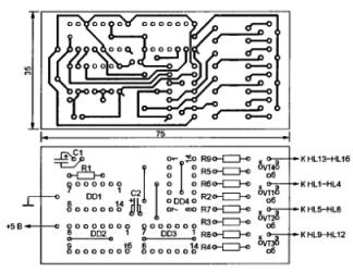
As mentioned above, the number of parts is small. Therefore, they all fit on one board, a drawing of which is shown in Figure 2.
Figure 2. Circuit board and location of parts (click on the picture to enlarge).
When making a board, you should pay attention to the fact that there are wire jumpers under the DD2, DD3, DD4 microcircuits. They must not be forgotten to install before soldering microcircuits. The chips themselves can be replaced by functional analogs from the K155, KR1533 series or by foreign analogues, which can be found on the Internet.
Each garland is assembled from LEDs of the same color.Now it is possible to use four colors: red, green, yellow and blue. If it is necessary to increase the number of LEDs in each garland, then the voltage supplying them should be increased, in our case it is + 12V, at the rate of about two volts for each additional LED. The voltage, of course, should not exceed the maximum permissible for key transistors. The resistance of the resistors R6 ... R9 should be selected so that the current through the LEDs does not exceed 20 ... 25 mA.
As a power source, you can use the Chinese adapter for + 12V voltage, supplementing it with an integral stabilizer of type 7805. It is necessary to obtain + 5V voltage to power the microcircuits. Since there are only four circuits, the stabilizer can work without a radiator.
Instead of LEDs, you can connect triac keysthen it will be possible to use garlands of incandescent lamps. The connection diagram can be found in the article “How to connect the load to the control unit on microcircuits”. Structurally, the keys can be executed on a separate board and connected to the controller by wires. Both boards should be placed in one case.
Boris Aladyshkin
See also at bgv.electricianexp.com
:


