Categories: Home automation, Industrial electrician, Programmable controllers
Number of views: 33778
Comments on the article: 0
LD Ladder Language and its Application
 The ladder or ladder diagram language LD (from the English Ladder Diagram) is an easy-to-use, graphical development language. It is based on relay-contact circuits, so the logic elements here are: relay windings, relay contacts, horizontal and vertical jumpers.
A pair of relay contacts or buttons are the main logical variables of the LD language, while the state of the variables is nothing more than the state of the contacts: open or closed.
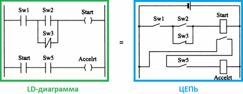
The program itself in this graphic language seems to be an analogue of the relay circuit, which can include many different functional blocks. In general, the syntax of the LD language makes it very easy to build logic circuits for relay technology.
A bit of history
As such, the language of relay circuits existed in the time of Thomas Edison, and only in the early 1970s it was adapted for first PLC. At the very beginning, this language appeared in the PLC programming packages of Modicon and Allen-Bradly companies, and the symbolism was borrowed precisely from the electrical field.
The LD language was originally intended for automation engineers working in enterprises. The programming interface visually presents the logic of the controller, makes it easy to solve commissioning tasks, and quickly find problems in the equipment connected to the PLC. The developers of the standard specially made the form so as to maximally facilitate the work of relay automation engineers on the PLC.

In the United States, for example, ladder language is the most common language. for PLC programming. It is also widely distributed around the world. The written program looks intuitively, so that any electrical engineer can easily read and understand it, because the logical operations here are presented in the form of an electric circuit with open and closed contacts.
The result of the logical operation "FALSE" or "TRUE" in the general case has the corresponding state of the circuit: if the current flows - "TRUE", "true", if there is no current - "FALSE", "false".
Advantages and disadvantages of the LD language
The main advantage of the language is certainly simplicity. The program is presented as an electric current, any specialist in electrical engineering will understand this. The rules are simple, only boolean expressions are used here, the code is rational and can be easily optimized manually.
Accordingly, the main drawback follows from this - operations are only binary, only discrete states are possible, continuous control immediately disappears. In addition, as the number of relays increases, the circuit becomes difficult to read, understand, and debug.
What does the program look like on LD
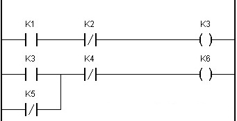
Two vertical lines represent a pair of supply rails. Between the tires are horizontally circuits, which include the winding and relay contacts. An arbitrary number of contacts can be set in the circuit. Serially connected contacts should close everything, then the current will go through the circuit, and the relay winding will receive power. Several relay windings can be connected in parallel, but not in series.

In the LD language, for each contact there is a logical variable that determines the state of the contact. For a normally open contact, the variable takes the value “TRUE” when the contact is closed, or takes the value “FALSE” when the contact is open. The label above the contact is the name of the variable and at the same time the name of the contact.
When several contacts are connected in series, the logic is equivalent to the “AND” operation. Parallel connected contacts reproduce the logical operation "mounting OR".The circuit is closed “ON”, open - “OFF”, which affects the state of the relay winding and the value of the logical variable with respect to the winding - “FALSE” or “TRUE”.
-
- || - normally open contact
-
- | / | - normally closed contact
-
- () - relay coil
-
- (/) - relay coil inverse
It is easy to see that the graphic symbols inside the LD diagram are intuitive, but they differ from those used in the electrical diagrams. Nevertheless, the fact that pseudo-graphic symbols serve to build a diagram (program) is an advantage of the language.
Inverse contacts (normally closed - | / | -) are characterized by the value of the TRUE variable when the contact is open, and the value of the FALSE variable when the contact is closed. The operation of such a contact is equivalent to a logical operation NOT. The combination of inverse and direct contact results in a switching contact.
In addition, as you see, the relay windings can also be inverse, which means that the logical variable takes an inverse value with respect to the state of the circuit: current flows - “FALSE”, no current - “TRUE”.
Language Examples LD:
Motor starting diagrams in the ladder diagram language LD for PLC
Examples of simple PLC programs in CodeSys in ladder language
Implementation of a through switch for automation of lighting control
Another very common PLC programming language:
See also at i.electricianexp.com
:

