Categories: Home automation, Programmable controllers
Number of views: 28074
Comments on the article: 0
Functional Block Diagram Language (FBD) and its Application
One of the most popular programming languages of PLCs - programmable logic controllers, is the graphic language of functional block diagrams FBD - Function Block Diagram. This language, along with other languages of IEC 61131-3, such as for example ladder logic language (LD), uses in its architecture a kind of electronic circuit.
A program written in this language for a controller consists of a certain list of circuits that are executed one after the other from top to bottom. In addition, there is the possibility of assigning labels to individual chains, in this case, the use of instructions to go to the label will be available in order to change the sequence of execution of chains, and create conditions and cycles.

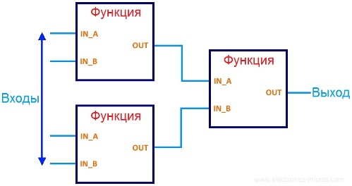
Thus, a program written in the graphic language FBD is a set of functional blocks connected to each other, the outputs and inputs of which are connected by communication lines. Communication lines reflect certain program variables through which data is exchanged from block to block.
A separate block carries a specific function (logical “and”, “not”, counter, etc.), while one block can have several outputs and inputs. Initially, the values of the variables are set by constants or from special inputs, and their outputs are connected further with other program variables or with the outputs of the PLC.
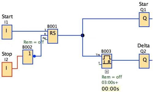
The figure shows an example program written in the functional block diagram language FBD. As you can see, this image of the program very clearly reflects the algorithm, which makes this language quite simple and convenient for developing software for PLCs.
In the process of programming in the FBD language, both standard blocks from libraries and blocks written in FBD or in other languages of the IEC 61131-3 standard are used. A block is a program element, a kind of subprogram, a function block or function (logical “NOT”, “OR”, “AND”, timer, counter, trigger, mathematical operation, processing of an analog signal, etc.).
Of these blocks, the expressions that form the chains are graphically compiled: the next block is connected to the output of one block, then another block, and so the chains are formed. In the course of the circuit, the order of execution of the blocks corresponds to the order of their connection, and the result of the execution of the circuit is either fed to the PLC output, or written to some internal variable.

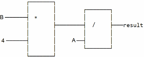
Consider a piece of the program written in the FBD language: Multiply by 4, then divide by A, and write the result into the variable result. In pseudocode, it will look like this: result: = B * 4 / A. It is also possible to add special control inputs EN and ENO outputs to the blocks to control the calls of individual blocks: a logic zero applied to the EN input will prohibit the call of this block, and the ENO output will report it in case of an error, and thereby interrupt the execution of the circuit to the end .
As you can see, the FBD language is extremely visual, convenient, and therefore easy to learn even by application specialists who do not have special training in computer science. The code is executed sequentially, the structure of the commands inside the code is simple, therefore the program is broadcast very quickly and the task is executed reliably.

There are various modifications of the FBD programming language, characterized by the presence of certain restrictions or extensions.
For example, there is a variant of FBC that allows the use of pure functions with only one output without intermediate variables - a modification for functional programming.
Or a modification of CFC (Continuous Function Chart), which allows you to set the order of chart execution not just by a sequential chain, but at the discretion of the software developer. With CFC, the developer gets more freedom, although the code is longer.
See also on this topic:PLC programming languages and CoDeSys automation software platform
See also at bgv.electricianexp.com
:
