Categories: Programmable controllers
Number of views: 2452
Comments on the article: 0
Examples of simple PLC programs in CodeSys in ladder language
This article shows an example of three simple programs. for programmable logic controllers (PLCs). All programs are written to automate control systems for various installations in the industry. They are educational in nature and can be used to teach PLC programming.
Earlier on this topic, we examined several typical solutions in PLC programs that can be used to control electric motors:Motor starting diagrams in the ladder diagram language LD for PLC
This collection covers the automation of the following processes:
-
Automatic system for dropping bottles;
-
Automatic selection of paint colors;
-
Automation of the ventilation system.
Technological ideas and illustrations. technological processes taken from the siteInstrumentationTools.
All programs are written in Codeys ladder language, in the English version it is Ladder Diagram, abbreviated LD.
In all examples, only the basic elements of this language are used - contacts and coils. The language of ladder diagrams also allows the use of a large number of additional elements - timers, counters, triggers, etc. More serious programs with all these elements will be discussed in the following articles.
Automatic bottle throwing system
Principle of operation: this system allows you to discard fallen bottles, which complicate the production process.
Process flow chart:
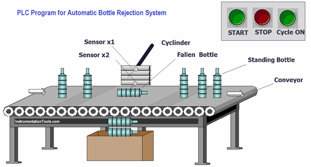
A conveyor belt is used to move bottles from one station to another. But before the bottles get to the gas station, it is necessary to make all the bottles worthwhile for further filling. A fallen bottle on a conveyor can create a problem in the following process, so here is a simple PLC program that processes a fallen bottle from a conveyor.
This process is carried out using sensors and actuators. When the conveyor is working, all bottles are moved from one station to another for the subsequent process. To detect standing and fallen bottles, two sensors and one pneumatic cylinder are used to push the fallen bottle off the conveyor.
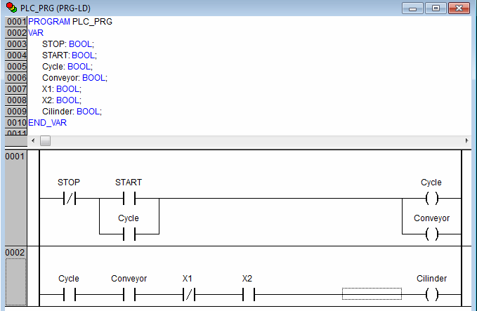
Ladder program for PLCin Codeys automatic bottle rejection system:
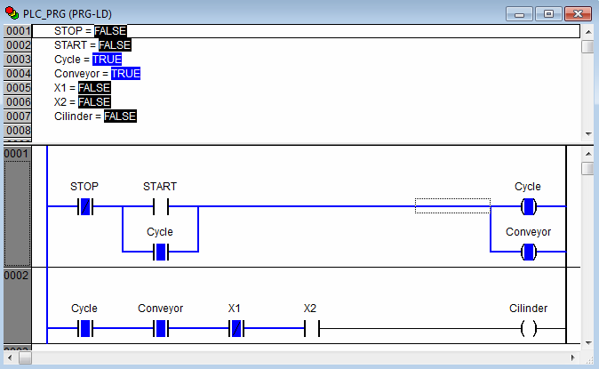
Program in emulation mode:
Description of the program:
Press the "START" button thereby feeding the circuit. The cycle and the pipeline start. In the second part of the circuit there are two induction sensors “X1” and “X2”, with the help of which the position of the bottle on the conveyor is determined. When the bottle fell, the “X2” sensor is triggered and its contact breaks the circuit, thereby not letting the dropped bottle fall.
When the bottles move along the conveyor belt, these sensors detect the position of the bottles whether they are standing or falling. Sensor X2 detects the bottom position of the bottle, and sensor X1 detects the top position of the bottle. If the sensor X2 detects the bottle, but the sensor X1 does not detect, then the pneumatic drive (Cilinder), and he will throw the bottle off the conveyor. After that, the remaining bottles will go to the water filling station and the whole cycle will be completed.
Bottle reset process:

Auto paint color selection
Principle of work: in this process, it was necessary to realize the automatic selection of the paint of the right color to fill.
Process flow chart:
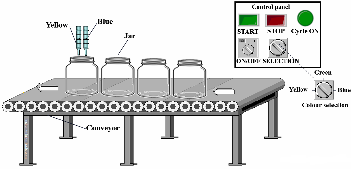
Here we have to fill in various paints in a jar as per requirement. So, consider 3 types of paint in different colors (yellow, blue and green). Two valves are used to supply ink.
As we know, mixing yellow and blue is green, so there is no need for a separate valve for green. When yellow and blue are filled at the same time, it will turn green.
A selector switch is used to select a color in the system, and an ON / OFF switch is used to stop the system.
PLC programin CodeSys:
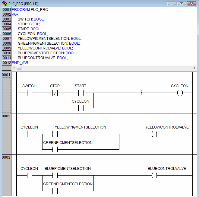
Description of the program:
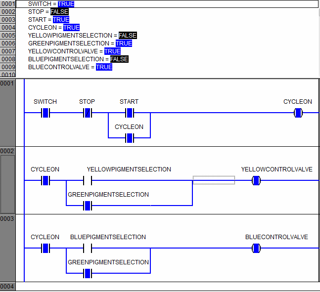
When the ON / OFF switch (I2.0) is in the ON position and the START button is pressed, the lamp lights CYCLEON. If the cycle is on and yellow paint is selected (YELLOWPIGMENTSELECTION), yellow control valve (YELLOWCONTROLVALVE) will be included. If the cycle is on and blue paint (BLUEPIGMENTSELECTION) is selected, the blue control valve (BLUECONTROLVALVE) will be turned on. If green color (GREENPIGMENTSELECTION) is selected, both valves will be turned on and the color will turn green.
The program in emulation mode (filling the bottle with green paint):
Ventilation system automation
PLC program for fan control systems for industry.
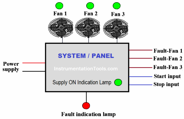
During operation of the system, any two of the three fans should work. To start any two fans - say, fan 2 and fan 3 - for each there are separate start and stop buttons.
Suppose that fan 2 and fan 3 are working, and one of them fails, then fan 1 should turn on automatically, i.e. two fans should be running at any given time. In the event of a malfunction of any two fans, the input power to the system should automatically turn off.
The “ON” status of the fans, as well as the status of the main power supply, must be indicated by the corresponding LED. If there is a malfunction with more than one fan, then this condition must be indicated by a blinking LED with a frequency of 5 Hz. A malfunction with a single fan or a malfunction with a fan should be indicated by a steady light on the malfunction status indicator.
This is a simple example of a fan control unit used in industry.
Process diagram:
PLC programin CodeSys:
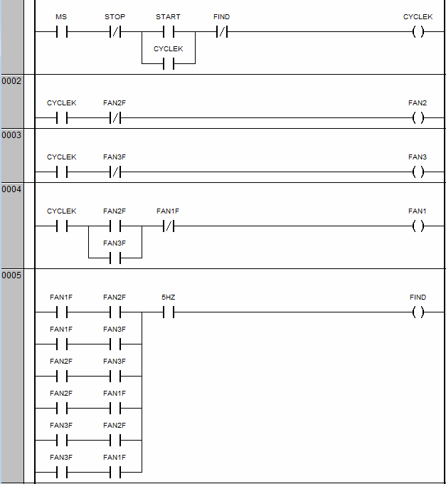
Continuation of the program:

Program description:
The program uses a cycle start circuit - CYCLEK coil. It can be started by pressing START, and stopped by pressing STOP. The main switch (MS) must be on.
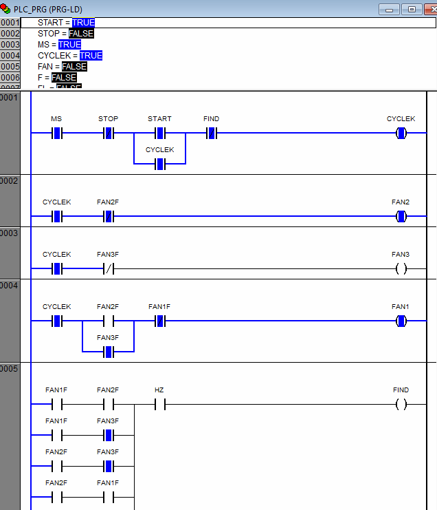
When the cycle is on (CYCLEK) and there is no malfunction of fan 2 and fan 3, fan 2 (FAN2) and fan 3 (FAN3) will be turned on. If fan 2 or fan 3 is faulty, fan 1 (FAN1) will start.
In the system, if any two of the three fans are faulty, the fault indication lamp (FIND) will flash at a frequency of 5 Hz. To do this, you need to use a special timer, but in order not to complicate the program, we will restrict ourselves to a separate contact in it for now. The indicator lamps for fan 1, fan 2 and fan 3 turn on in accordance with the fault signal.
Program in emulation mode (case of fan breakdown 3):
All of the above programs are very simple and primarily designed to obtain basic knowledge in learning the language of real-life diagrams. In the following articles we will consider more complex examples.
See also at i.electricianexp.com
:
