Categories: Programmable controllers
Number of views: 7314
Comments on the article: 0
An example of upgrading the electrical circuit of a pumping station with two pumps to a circuit controlled by PLC
In the reviews of the previous article on this topic - An example of upgrading the electrical circuit of a freight elevator using a programmable controller (PLC) there was a desire to make material with a more detailed step-by-step analysis of the process of writing a program in CFC inCoDeSys. Since it’s not very interesting to reassemble the circuit from the previous article, this time we’ll take something else as an example, for example, the once very popular circuit of a pumping station with pumping pumps.
The device and principle of operation of the pumping station
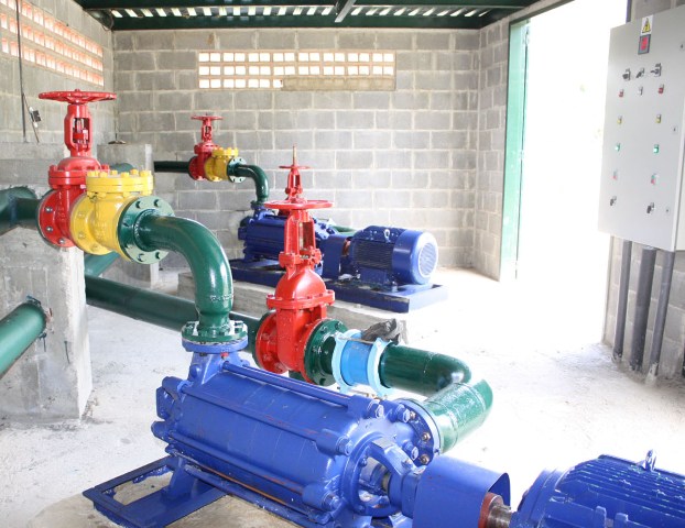
So, there is a drainage type pumping station with two pumps. Water rushes into the tank by gravity, and the task of the pumps is to pump it out of this tank to prevent overfilling. One of the pumps according to the scheme is the main, the second is the backup. The scheme provides for the possibility of assigning a primary and backup pump using a switch.
Initially, the pump is turned on, which is designated as the main one, and if it cannot cope with pumping out the liquid, the standby pump is automatically turned on to its aid. If both pumps cannot pump out the liquid, then a light and sound alarm is triggered.
The principle of operation of the control circuit
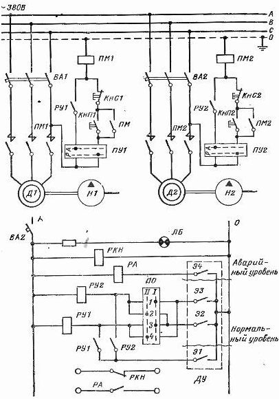
Fluid level is controlled level sensors with 4 pins. When the liquid rises in the tank, the contacts close in turn, supply power to the coil intermediate electromagnetic relayswhose contacts are included in a chain of coils of electromagnetic starterscontrolling electric motors of pumps.
Schematic diagram of the electrical pumping station with two pumping pumps:
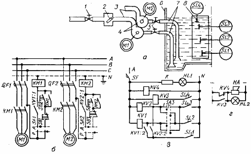
There is another version of this scheme with designations made according to modern GOSTs (1 and 5 - valves, 2 - valves, 3 - discharge pipelines, 4 - pumps, 6 - reservoir, 7 - suction pipelines, 8 - electrode):
An example of current flow through the circuits according to the first scheme (with the first main pump and the second backup pump, the software switch is in position 1):
1) When water reaches the level of E1 - nothing happens,
2) When the water reaches the level of E2 - the relay coil RU1 is activated, closes its contacts, incl. the contact in the PM1 starter circuit is turned on, the D1 motor is turned on.
3) When the water reaches the level of E3 - the relay coil RU2 is activated, while the relay RU1 is also turned on and the D1 engine is running. Relay RU2 closes its contacts, incl. the contact in the PM2 starter circuit is turned on, the D2 motor is turned on.
4) When the water reaches the level of E4 - relay RA is activated. The contacts of this relay are included in a separate circuit for an independent power source, for example, a battery (not shown in the first circuit). There is also connected the contact of the LV voltage relay. In the absence of voltage or an emergency liquid level, an alarm lamp and a bell sound (they are not shown in the first diagram either).
The scheme of the pumping station can operate in automatic and manual modes. The choice of operating mode for each pump is carried out individually using the switches PU1 and PU2. And in manual mode, turning on and off the electromagnetic starters and pump motors is performed using the buttons KnP and Kns.
Circuit upgrade
We will modernize the relay control circuit of the pumping station. After upgrading, the pumping liquid will programmable logic controller (PLC). In this case, any type of controller can be used as a PLC. In our case, even some inexpensive one is perfect. programmable relay.

Since the task of this article is purely educational - give initial PLC programming skills, then we will use for this very convenient software package CodeSyS 2.3 and controller company Aries. Controller model requires CodeSyS when creating a project in the program. We will make up the program in CFC language.
This project was solely for educational purposes. Our task is to replace the control circuit from relay to software, without changing anything in the device, technology and controls of the pumping station.
First, we define all the necessary input and output signals that we need in the program.
Inputs
-
Start 1 pump;
-
Stop 1 pump;
-
Start 2 pumps;
-
Stop 2 pumps;
-
Manual mode 1 pump;
-
Automatic mode 1 pump;
-
Manual mode 2 pumps;
-
Automatic mode 2 pumps;
-
1st main pump;
-
2nd main pump;
-
Level sensor DN1;
-
Level sensor DN2;
-
Level sensor DN3;
-
DN4 level sensor.
Outputs:
-
Pump1;
-
Pump2;
-
Emergency lamp.
Total: 14 inputs and 3 exit.
1. Create a manual pump control program.
The pump motor must be switched on when the Start button is triggered and there is a signal at the input "Manual mode". Disable when you press the "Stop" button and when there is a signal at the input "Manual mode", and also separately if there is no signal at the input "Manual mode".
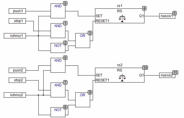
For this we use RStrigger on the input of which (SET) give a signal from the start button (pusk1) and input "Manual mode" (ruhnoy1) through the element AND (logical "AND"). The trigger will fire and switch its output (Q1) only when there are logical units on both inputs (TRUE).
In order to turn off the pump at the trigger input (RESET1) logical unit should come (TRUE). In one case, this occurs when there is a signal from the Stop button (stop1) and at the same time the signal is present at the Manual mode input (ruhnoy1). To do this, they are combined by an element AND. Everything is the same here, as in the case of the pump start-up process.
In the second case, the logical unit must come on trigger input (RESET1) when the switch is off and there is no signal at the input "Manual mode", that is, regardless of what state the pump is in, when the switch is switched from the position "Manual mode" to the position "Automatic mode", the engine must be switched off. To do this, invert the input signal ruhnoy1 and combine them with a pump shutdown signal through the element OR (logical OR).
In this case, the trigger input (RESET1) a logical unit may come in two ways. In the first case, it comes from an element ANDproviding shutdown from the button and when disconnecting the input associated with the installation of the manual mode. In the second case, logical zero (FALSE) turns at the exit NOT to logical unit (TRUE).

Since we have 2 pumps in the circuit that operate in the same mode in manual mode, we will add another same code fragment to the program.
2. Create a program for the circuit to work in automatic mode
To facilitate understanding of the operation of the circuit, we will initially make a program without taking into account the switches for selecting the operating mode and selecting the main pump, i.e. Suppose we need a circuit that includes a first pump for a second level sensor, a second pump for a third sensor. When the fourth sensor is triggered, an alarm is triggered. The shutdown of both pumps is carried out after complete pumping of water and the first level sensor is triggered. For this we need two triggers. RSthat will connect all the inputs and outputs we need in the right way.
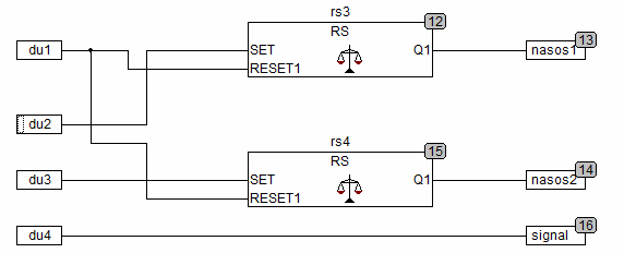
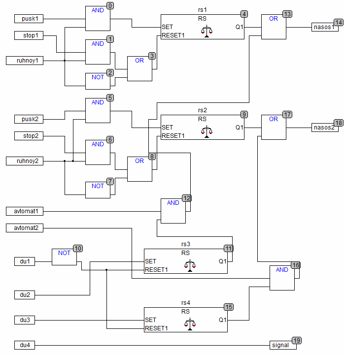
But not everything is as simple as it seems at first glance. If we try to check this program in the emulation mode, while simulating the alternate actuation of the contacts of the level sensor about rising water, we will see that when the water rises to the second sensor, the pump does not turn on. The culprit is the first contact of the level sensor, which sends a signal to the tripping input of the triggers. But we need the triggers to turn off only when disconnecting 1 contact of the level sensor.To do this, after contact du1 put item NOT, which will invert the signal from the sensor and the triggers will be reset then only when the input contact is disconnected.

Now add to the circuit the contacts of the switches of the automatic mode. Pump motors should only be switched on when there is a signal at the inputs to which the contacts of these switches are connected (logical unit). Moreover, each engine has its own switch in the circuit.
For this in add 2 elements to the scheme AND, which will allow turning on the pumps only when the switches are turned on in automatic mode and 2 elements OR which will link manual and automatic mode. Thanks to them, the outputs controlling the starters of the nasos1 and nasos2 pumps can receive a signal both from manual triggers and from automatic triggers.
3. Add a pump selection switch
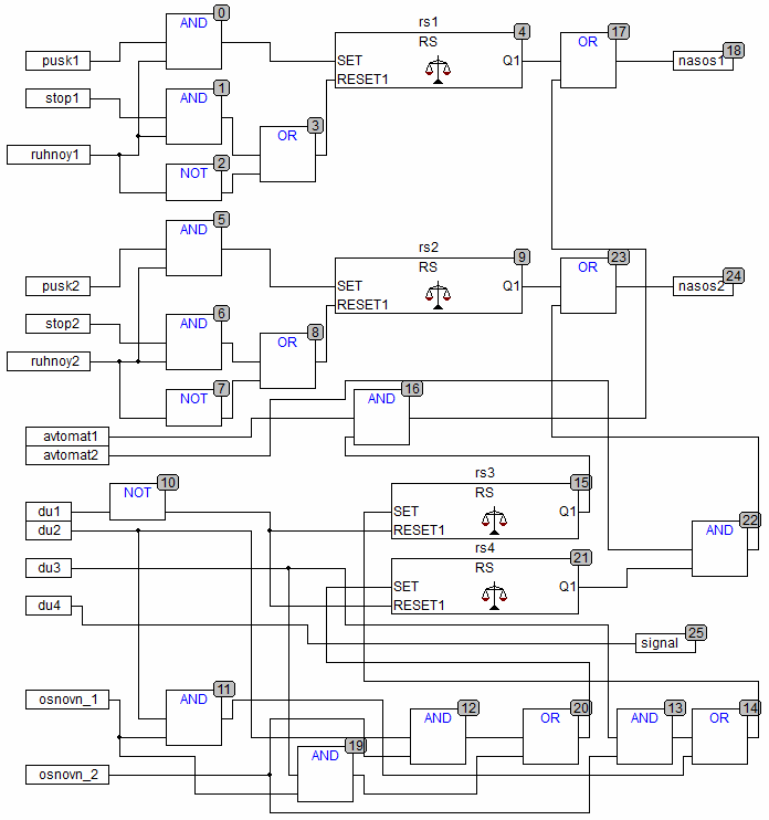
At this stage, it remains to add a switch to the circuit, which allows you to select the main and backup pump. The main pump is turned on first, the backup - second. Physically on the switches in the electrical circuit there are 4 inputs and 4 outputs. We will use 2 outputs to connect the programmable controller. 2 others will be parallelized by the 2nd main.
In the program for the PLC, we need to enter 2 input signals - "Primary 1 pump" (osnovn_1) and "Primary 2 pump" (osnovn_2). First we add 2 elements AND and connect the inputs of the triggers through them. A signal from the second contact of the level sensor and from its switch input comes to each element.
We carry out similar actions with the third contact of the sensor and the inputs of the switch. And in order to get 2 signals for each trigger input, add 2 more elements to the circuit OR.
The final program of the pumping station with two pumping pumps for the programmable controller:
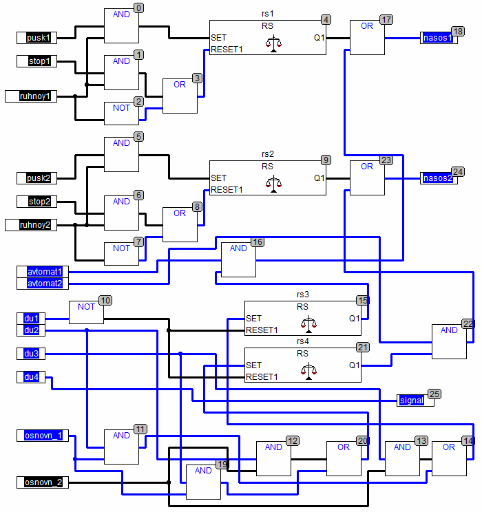
A written program, even in the absence of a programmable controller, can be checked in emulation mode inCodeSyS (Online - Emulation Mode - Connection - Ctrl + f7 - Start F5).
Program in emulation mode inCodeSyS:
If you have any questions, then leave them in the comments! In your opinion, is it worth continuing to make articles on this topic?
See also at bgv.electricianexp.com
:
