Categories: Programmable controllers
Number of views: 4966
Comments on the article: 0
Motor starting diagrams in the ladder diagram language LD for PLC
With this article, we begin a series of training materials for creating programs for programmable logic controllers (PLCs) in the CodeSys environment. It is best to learn how to program PLCs using real-life practical examples.
Consider a few simple programs that you can use to control squirrel cage induction motors. To create the programs, we will use the LD ladder diagram language in CodeSys.
In total, we consider 4 programs for 4 schemes:
1. Scheme of turning the engine on and off;
2. The control circuit of the reversible engine using the intermediate digging “Stop”;
3. The control circuit of the reversible engine without the use of an intermediate digging “Stop”;
4. The control circuit of a reversible motor using limit switches.
The examples below are primarily for educational purposes, as it is not practical to use PLC for such simple circuits.
Ladder Diagram Language, LD) in the Russian-language documentation for the PLC is often called language of relay-contact circuits (RKS). This graphic language was invented in the 70s of the XX century and primarily it was created for electricians who at that time had to upgrade relay-contact circuits with discrete devices (relays, timers, counters, etc.) into circuits with using programmable controllers. He has been a leader in popularity for a long time. among all IEC PLC programming languages.
The LD language (RKS) almost completely repeats the logic of the relay-contact electrical circuits. On the left and right are the vertical circuits, which are considered power buses. Between them there are horizontal circuits, in each of which on the left there are various normally open and normally closed contacts, and on the right side there are windings (coils).
Each contact corresponds to its own logical variable (ON or OF), which transmit the Boolean state “True” or “False” to the coil. In the first case, the coil receives the value "on" (ON), in the second - "off" (OFF).
In this language, it is quite easy to create complex circuits including various functional blocks (triggers, timers, counters, etc.), which allows you to use this language to solve almost any, even very complex tasks.
Engine on and off circuit
The first version of the program completely repeats the most common circuit using two buttons and an electromagnetic starter.
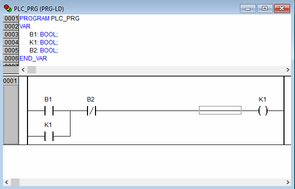
The “start” button (B1), when pressed, supplies the value of a logical unit (“True”) through the closed contact of the stop button (B2) to the winding (K1). A winding contact connected in parallel to the contact of the first button is turned on and creates an interlock circuit that energizes the winding when the start button is released.
This circuit can be simplified using the “Set” and “Reset” coils (analogue of the RS trigger). These are very commonly used components of the LD language. In programs, they are designed to remember the state of turning on and off the electric motor or any other output element. In addition to controlling motors with other actuators of the coil, Set / Reset is often used to track parts on the machine.
Since the LD language is developed on the basis of the operation of relay-contact logic devices, the “Set” and “Reset” coils have their own physical prototype relay in the past, the so-called “blocking relays”. They were often used to memorize the state of operation of the control object during a power outage.
These were relays with two installation and reset coils.When power was supplied to the mounting coil, it shifted the internal mechanism to the “on” position and this position was maintained mechanically by means of a latch.
The power supply to the reset coil led to the displacement of the internal mechanism to the off position. If none of the coils were energized, the relay would remain in its last position. Hence the name - “blocking relay”.
In the program below, when a pulse signal is applied to the “Set” coil, it is activated and remains on until a pulse signal is sent to the “Reset” coil.
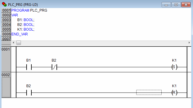
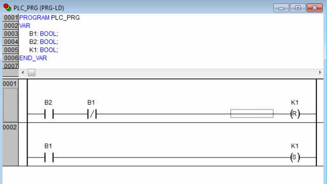
In this circuit, if two buttons are pressed at the same time (both “Set” and “Reset” modes are active), the coil will be disabled. You can also change the logic and change the priority of the “Set” and “Reset” modes. In this case, when two buttons are pressed simultaneously, the coil will remain on.
Scheme in emulation mode:
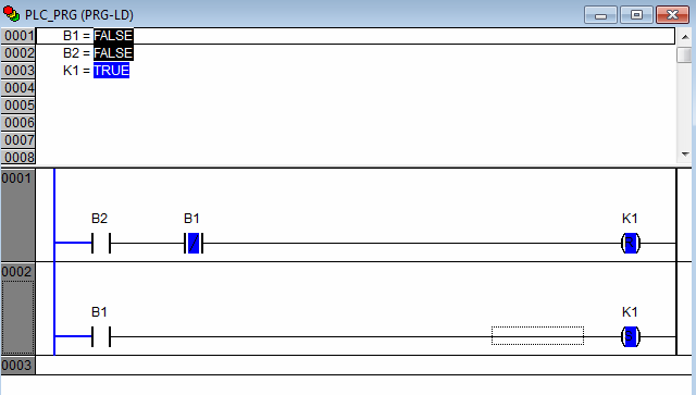
To enable the emulation mode in CodeSys you need to check the “Emulation mode” checkbox in the “Online” menu item, then “Start” (F5) and after setting the required contact values, write these values to the controller, in this case virtual pressing “Ctrl + F7”.
Reverse circuits engine on and off
Now we turn to the control circuits of a reversible squirrel-cage electric motor. The program below allows the motor to be reversed using the Forward (B2) and Back buttons (B3) after pressing the intermediate Stop button (B1) before each change in the direction of rotation.
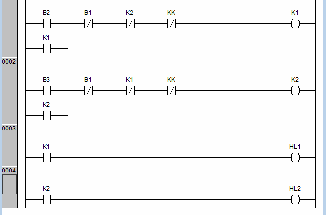
The normally-closed interlocking contacts K1 and K2 make it impossible to turn on the motor for a short circuit while pressing the Forward and Back buttons.
Any additional blocking contacts are connected in series with the coils, for example, in the program it thermal relay contacts QC.
HL1 and HL2 are coils responsible for turning on the warning lights. From them it is possible to determine when the motor rotates in which direction.
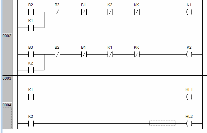
Often, a program is used to control the electric motor, which repeats the relay-contact circuit using two paired contacts on the buttons. Such a scheme allows you to change the direction of rotation of the electric motor without using the intermediate Stop button. This button is used only when the motor stops completely.
An example of such an LD scheme in CodeSys:
All of the above LD programs are quite simple and very well received by electricians. In conclusion, we present a more complex program using timers (software analogues of a time relay).
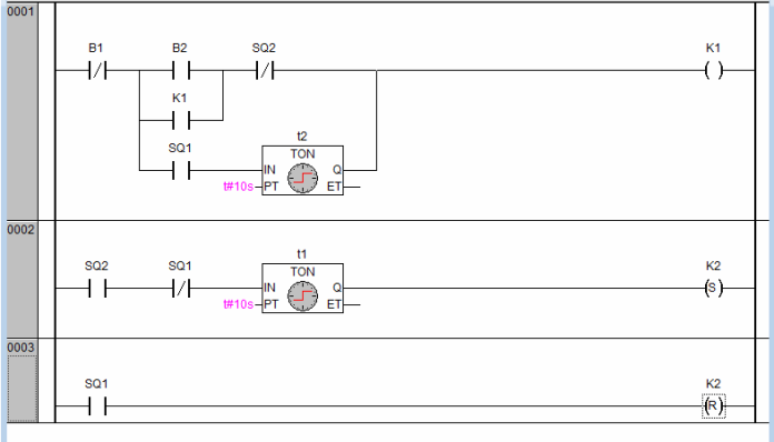
This program allows you to control the automatic movement of the reversible electric motor between two points with a shutter speed. After pressing the “Start” button (B2), the mechanism controlled by the electric motor moves from point A to point B. There it stops for 10 seconds and starts moving in the opposite direction. At point A, a new stop for 10 seconds and a reverse movement to point B.
Motion control is carried out using two limit switches (SQ1 and SQ2), and the time delays on the stops are provided using two TON timers. We will tell you about the types of CodeSys timers and the features of their use in programs in one of the following articles on teaching PLC programming.
See also at bgv.electricianexp.com
:
