Categories: Featured Articles » Home automation
Number of views: 149188
Comments on the article: 5
The principle of operation and the basics of PLC programming
Programmable Logic Controllers (PLCs)
 Before the advent of solid-state logic circuits, the development of logical control systems was based on electromechanical relays. To this day, the relays are not outdated in their destination, but nevertheless in some of their previous functions they are replaced by a controller.
In modern industry there are a large number of different systems and processes that require automation, but now such systems are rarely designed from relays. Modern production processes need a device that is programmed to perform various logical functions. In the late 1960s, the American company Bedford Associates developed a computer device called MODICON (Modular Digital Controller). Later, the name of the device became the name of the unit of the company that designed, made and sold it.
Other companies developed their own versions of this device, and in the end, it became known as PLC, or programmable logic controller. The goal of a programmable controller capable of simulating the operation of a large number of relays was to replace electromechanical relays with logic elements.
The PLC has a set of input terminals with which you can monitor the status of sensors and switches. There are also output terminals that provide a “high” or “low” signal to power indicators, solenoid valves, contactors, small motors, and other self-monitoring devices.
PLCs are easy to program because their programming language resembles the logic of a relay. So an ordinary industrial electrician or an electrical engineer, accustomed to reading ladder logic circuits, will feel comfortable when programming a PLC to perform the same functions.
Signal connection and standard programming are somewhat different for different PLC models, but they are quite similar, which allows you to place here a “general” introduction to the programming of this device.
The following illustration shows a simple PLC, or rather, how it might look in front. Two screw terminals for connecting internal PLC circuits up to 120 VAC are marked L1 and L2.
Six screw terminals located on the left side provide connection for input devices. Each terminal represents its input channel (X). The screw terminal (“general” connection) located in the lower left corner is usually connected to the L2 (neutral) current source with a voltage of 120 V AC.

Inside the PLC housing that connects each input terminal to a common terminal, there is a device isolator (LED) that provides an electrically isolated “high” signal for the computer circuit (a phototransistor interprets the LED light) when a 120-volt alternating current is installed between the corresponding input terminal and the common terminal. The LED on the front of the PLC makes it possible to understand which input is live:

The output signals are generated by PLC computer circuitry, activating a switching device (transistor, thyristor, or even an electromechanical relay) and connecting the “Source” terminal (lower right corner) to any output marked with a letter Y. The Source terminal is usually associated with L1. Just like every input, each output that is energized is marked with an LED:

Thus, the PLC can be connected to any devices, such as switches and electromagnets.
PLC programming basics
The modern logic of the control system is installed in the PLC through a computer program.This program determines which outputs are live and under what input conditions. Although the program itself resembles a relay logic circuit, there are no switch contacts or relay coils operating inside the PLC to create connections between input and output. These contacts and coils are imaginary. The program is written and viewed using a personal computer connected to the PLC programming port.
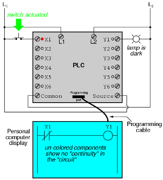
Consider the following circuit and PLC program:

When the push-button switch is not activated (in the off state), the signal is not sent to input X1. In accordance with the program, which shows the "open" input X1, the signal will not be sent to the output Y1. Thus, the output Y1 will remain de-energized, and the indicator connected to it will turn off.
If the push button switch is pressed, the signal will be sent to input X1. All contacts X1 in the program will assume an activated state, as if they are relay contacts activated by supplying voltage to a relay coil called X1. In this case, open contact X1 will be “closed” and send a signal to coil Y1. When coil Y1 is energized, output Y1 will light up with a bulb connected to it.

It should be understood that contact X1 and coil Y1 are connected using wires, and the “signal” appearing on the computer monitor is virtual. They do not exist as real electrical components. They are present only in a computer program - part of the software - and just resemble what is happening in the relay circuit.
It is equally important to understand that the computer used to write and edit the program is not needed for further use of the PLC. After the program has been loaded into the programmable controller, the computer can be turned off, and the PLC will independently execute program commands. We include a personal computer monitor in the illustration so that you understand the connection between real conditions (switch closure and lamp statuses) and program statuses (signals through virtual contacts and virtual coils).
The true power and versatility of the PLC is revealed when we want to change the behavior of the control system. Since the PLC is a programmable device, we can change the commands that we set up without reconfiguring the components connected to it. Suppose that we have decided to switch the function “switch - light bulb” the other way around: press the button to turn off the light, and release it to turn it on.
The solution to this problem in real conditions is that the switch, "open" under normal conditions, is replaced by a "closed". Its software solution is changing the program so that contact X1 under normal conditions is "closed" and not "open".
In the following image you will see a program already changed, with the switch not activated:

And here the switch is activated:
One of the advantages of implementing logical control in software, as opposed to control using hardware, is that the input signals can be used as many times as needed. For example, consider a circuit and a program designed to turn on a light bulb if at least two of the three switches are activated at the same time:

To build a similar circuit using a relay, three relays with two open contacts will be required under normal conditions, each of which must be used. However, using the PLC, we can program as many pins for each “X” input as we would like without adding any additional equipment (each input and output should occupy no more than 1 bit in the PLC digital memory) and call them as many times as necessary .
In addition, since each PLC output occupies no more than one bit in its memory, we can add contacts to the program, bringing the Y output to an unactivated state. For example, take an engine diagram with a system to control the start of movement and stop:

The switch connected to input X1 serves as the “Start” button, while the switch connected to input X2 serves as the “Stop” button. Another contact, named Y1, like printing in contact, allows the motor contactor to remain energized even if you release the Start button. In this case, you can see how the contact X2, "closed" under normal conditions, appears in the color block, thereby showing that it is in the "closed" ("electrically conductive") state.
If you press the "Start" button, then a current will pass through the "closed" contact X1 and it will send 120 VAC to the motor contactor. The parallel contact Y1 will also “close”, thereby closing the circuit:

If we now press the "Start" button, contact X1 will go into the "open" state, but the motor will continue to work, because the closed contact Y1 will still keep the coil energized:

To stop the engine, you need to quickly press the "Stop" button, which will report the voltage to the input X1 and the "open" contact, which will lead to the termination of the voltage supply to the coil Y1:

When you pressed the “Stop” button, input X1 was left without voltage, thereby returning contact X1 to its normal “closed” state. Under no circumstances will the engine run again until you press the Start button again, because the print in pin Y1 has been lost:

A fault-tolerant model of PLC control devices is very important, as is the case with electromechanical relay control devices. It is always necessary to take into account the effect of a mistakenly “open” contact on the system. So, for example, in our case, if contact X2 is erroneously “opened”, there will be no way to stop the engine!
The solution to this problem is to reprogram the contact X2 inside the PLC and actually press the Stop button:

When the “Stop” button is not pressed, the input of the PLC X2 is energized, i.e. contact X2 is “closed”. This allows the motor to start operation when current is communicated to terminal X1, and to continue operation when the "Start" button is released. When you press the “Stop” button, contact X2 goes into the “open” state and the engine stops working. Thus, you can see that there is no functional difference between this and the previous model.
However, if the input terminal X2 was erroneously “opened”, the input X2 can be stopped by pressing the “Stop” button. As a result, the engine shuts off immediately. This model is safer than the previous one, where pressing the “Stop” button will make it impossible to stop the engine.
In addition to the inputs (X) and outputs (Y) in the PLC, it is possible to use “internal contacts and coils. They are used in the same way as intermediate relays used in standard relay circuits.
To understand the principle of operation of the “internal” circuits and contacts, consider the following circuit and program developed on the basis of the three inputs of the logical function AND:

In this circuit, the lamp is on until one of the buttons is pressed. In order to turn off the lamp, press all three buttons:

This article on programmable logic controllers illustrates only a small sample of their capabilities. As a PLC computer, it can perform other advanced functions with much greater accuracy and reliability than when using electromechanical logic devices. Most PLCs have more than six inputs and outputs. The following illustration shows one of Allen-Bradley's PLCs:

With modules, each of which has 16 inputs and outputs, this PLC has the ability to control a dozen devices.A PLC placed in the control cabinet takes up little space (for electromechanical relays that perform the same functions, much more free space would be required).

One of the advantages of the PLC, which simply cannot be duplicated by an electromechanical relay, is remote monitoring and control via the computer’s digital network. Since a PLC is nothing more than a specialized digital computer, it can easily "talk" to other computers. The next photo is a graphical representation of the liquid filling process (pumping station for municipal wastewater treatment) controlled by a PLC. Moreover, the station itself is located a few kilometers from the computer monitor.
See also at bgv.electricianexp.com
: