Categories: Featured Articles » Practical Electronics
Number of views: 59798
Comments on the article: 0
Drivers for MOSFET transistors on a 555 timer
 Integral timer 555 found another application in three-phase inverters, or as they are often called frequency-controlled drives. The main purpose of "chastotnikov" is the regulation of the rotational speed of three-phase asynchronous motors. In literature and on the Internet you can find a lot homemade frequency drive circuits, interest in which has not disappeared to date.
The whole idea is this. The rectified mains voltage with the help of the controller is converted to three-phase, as in an industrial network. But the frequency of this voltage can change under the influence of the controller. The ways of changing are different, from simple manual control to regulation automation system.
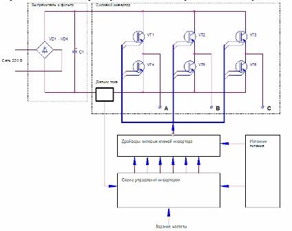
The block diagram of the three-phase inverter is shown in Figure 1. Points A, B, C show the three phases to which the induction motor is connected. These phases are obtained by switching transistor switches, as shown in this figure. special transistors IGBT.
Figure 1. Block diagram of a three-phase inverter
Between the control device (controller) and power keys, the drivers of the inverter power keys are installed. As drivers, specialized chips like IR2130 are used, which allow you to connect all six keys to the controller at once - three upper and three lower ones, and in addition it also provides a whole range of protections. All details about this chip can be found in the Data Sheet.
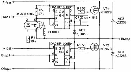
And everything would be fine, but for a home experiment such a chip is too expensive. And here again our old friend comes to the rescue integral timer 555He is KR1006VI1. A diagram of one arm of a three-phase bridge is shown in Figure 2.

Figure 2. Drivers for MOSFETs on a 555 timer
The drivers of the upper and lower keys of the power transistors are KR1006VI1 operating in the Schmitt trigger mode. When using the timer in this mode, it is enough to simply obtain a pulsed gate opening current of at least 200 mA, which ensures fast switching of the output transistors.
The lower key transistors are connected directly to the controller’s common wire, therefore, there are no difficulties in controlling the drivers — the lower drivers are controlled directly by the logic signals from the controller.
The situation with the upper keys is somewhat more complicated. First of all, you should pay attention to how the drivers of the upper keys are powered. This way of eating is called "brisk." Its meaning is as follows. The DA1 chip is powered by capacitor C1. But how can it be charged?
When the transistor VT2 opens, the minus lining of the capacitor C1 is almost connected to the common wire. At this time, the capacitor C1 is charged from the power source through the diode VD1 to a voltage of + 12V. When the transistor VT2 closes, the diode VD1 will also be closed, but the energy reserve in the capacitor C1 is enough to trigger the DA1 chip in the next cycle. To carry out galvanic isolation from the controller and among themselves, the control of the upper keys must be carried out through the optocoupler U1.
This method of supply allows you to get rid of the complexity of the power supply, to do with just one voltage. Otherwise, three isolated windings on the transformer, three rectifiers and three stabilizers would be required. In more detail with this method of supply can be found in the descriptions of specialized microcircuits.
Boris Aladyshkin
See also at i.electricianexp.com
:

