Categories: Featured Articles » Practical Electronics
Number of views: 368329
Comments on the article: 5
Schemes of amateur frequency converters
 One of the first inverter circuits for powering a three-phase motor was published in Radio magazine No. 11 of 1999. Scheme developer M. Mukhin at that time was a student of grade 10 and was engaged in a radio circle.
The converter was intended to power the miniature three-phase motor DID-5TA, which was used in the machine for drilling printed circuit boards. It should be noted that the operating frequency of this engine is 400Hz, and the supply voltage is 27V. In addition, the midpoint of the motor (when connecting the windings with a “star”) was brought out, which made it possible to extremely simplify the circuit: it took only three output signals, and each phase required only one output key. The generator circuit is shown in Figure 1.
As can be seen from the diagram, the converter consists of three parts: a three-phase sequence pulse generator-generator on DD1 ... DD3 microcircuits, three keys on composite transistors (VT1 ... VT6) and the actual electric motor M1.
Figure 2 shows the timing diagrams of pulses generated by the generator generator. The master oscillator is made on the DD1 chip. Using resistor R2, you can set the desired engine speed, as well as change it within certain limits. More detailed information about the circuit can be found in the above log. It should be noted that, according to modern terminology, such generators are called controllers.

Picture 1.
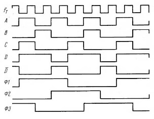
Figure 2. Timing diagrams of the generator pulses.
Based on the controller A. Dubrovsky from the city of Novopolotsk, Vitebsk region. The design of a variable frequency drive for an engine powered by 220V AC was developed. The circuit diagram was published in the journal Radio 2001. Number 4.
In this scheme, practically unchanged, the just reviewed controller is used according to the scheme of M. Mukhin. The output signals from the elements DD3.2, DD3.3 and DD3.4 are used to control the output keys A1, A2, and A3, to which the electric motor is connected. The diagram shows the key A1, the rest are identical. A complete diagram of the device is shown in Figure 3.

Figure 3
Connecting the motor to the output of a three-phase inverter
To familiarize yourself with the connection of the engine to the output keys, it is worth considering a simplified diagram shown in Figure 4.

Figure 4
The figure shows the motor M, controlled by keys V1 ... V6. Semiconductor elements to simplify the circuit shown in the form of mechanical contacts. The electric motor is powered by a constant voltage Ud obtained from the rectifier (not shown in the figure). In this case, the keys V1, V3, V5 are called upper, and the keys V2, V4, V6 lower.
It is quite obvious that the opening of the upper and lower keys at the same time, namely with the pairs V1 & V6, V3 & V6, V5 & V2, is completely unacceptable: a short circuit will occur. Therefore, for the normal operation of such a key scheme, it is imperative that by the time the lower key is opened, the upper key has already been closed. To this end, the controllers form a pause, often referred to as a “dead zone".
The magnitude of this pause is such as to ensure guaranteed closure of power transistors. If this pause is insufficient, it is possible to briefly open the upper and lower keys at the same time. This causes the output transistors to heat, often leading to their failure. This situation is called through currents.
Let us return to the circuit shown in Figure 3. In this case, the upper switches are transistors 1VT3, and the lower ones 1VT6. It is easy to see that the lower keys are galvanically connected to the control device and among themselves.Therefore, the control signal from the output 3 of the element DD3.2 through the resistors 1R1 and 1R3 are fed directly to the base of the composite transistor 1VT4 ... 1VT5. This composite transistor is nothing but a lower key driver. Exactly also from the elements DD3, DD4, the composite transistors of the lower key driver of channels A2 and A3 are controlled. All three channels are powered by the same rectifier. on the diode bridge VD2.
The upper keys of galvanic communication with a common wire and control device do not have, therefore, to control them, in addition to the driver, on a composite transistor 1VT1 ... 1VT2, an additional optocoupler 1U1 had to be installed in each channel. The output optocoupler transistor in this circuit also performs the function of an additional inverter: when the output 3 of the DD3.2 element is a high level, the transistor of the upper switch 1VT3 is open.
A separate rectifier 1VD1, 1C1 is used to power each top-key driver. Each rectifier is powered by an individual transformer winding, which can be considered as a drawback of the circuit.
The capacitor 1C2 provides a key switching delay of about 100 microseconds, the optocoupler 1U1 gives the same amount, thereby forming the aforementioned "dead zone".
Is frequency regulation enough?
With a decrease in the frequency of the supply alternating voltage, the inductive resistance of the motor windings drops (just remember the inductive resistance formula), which leads to an increase in the current through the windings, and, as a result, to overheating of the windings. Also, the stator magnetic circuit is saturated. To avoid these negative consequences, when the frequency decreases, the effective value of the voltage on the motor windings must also be reduced.
One way to solve the problem in amateur chastotniks was proposed to regulate this most effective value with the help of LATR, the movable contact of which had a mechanical connection with a variable resistor of the frequency regulator. This method was recommended in the article by S. Kalugin, “Finalization of the speed controller of three-phase asynchronous motors”. Journal of Radio 2002, No. 3, p. 31.
In amateur conditions, the mechanical assembly turned out to be complex and, most importantly, unreliable. A simpler and more reliable way to use an autotransformer was proposed by E. Muradkhanian from Yerevan in Radio magazine No. 12 2004. A diagram of this device is shown in Figures 5 and 6.
The mains voltage of 220V is supplied to the autotransformer T1, and from its movable contact to the rectifier bridge VD1 with a filter C1, L1, C2. At the filter output, a variable constant voltage Ureg is obtained, which is used to power the motor itself.
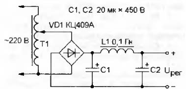
Figure 5
The voltage Ureg through the resistor R1 is also supplied to the master oscillator DA1, made on the chip KR1006VI1 (imported version NE555) As a result of this connection, a conventional square-wave generator turns into a VCO (voltage-controlled generator). Therefore, with an increase in voltage Ureg, the frequency of the generator DA1 also increases, which leads to an increase in the engine speed. With a decrease in voltage Ureg, the frequency of the master oscillator also decreases proportionally, which avoids overheating of the windings and the supersaturation of the stator magnetic circuit.

Figure 6
In the same journal article, the author offers a variant of the master oscillator, which allows you to get rid of the use of an autotransformer. The generator circuit is shown in Figure 7.
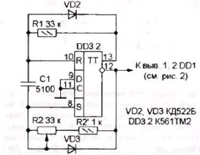
Figure 7
The generator is made on the second trigger of the DD3 chip, in the diagram it is designated as DD3.2. The frequency is set by capacitor C1, the frequency is controlled by a variable resistor R2. Together with the frequency control, the pulse duration at the generator output also changes: with decreasing frequency, the duration decreases, so the voltage on the motor windings drops. This control principle is called pulse width modulation (PWM).
In the amateur circuit under consideration, the engine power is small, the engine is powered by rectangular pulses, so the PWM is quite primitive. In real industrial frequency converters high power PWM is designed to generate almost sinusoidal voltage at the output, as shown in Figure 8, and to implement work with various loads: at constant torque, at constant power and at fan load.

Figure 8. The shape of the output voltage of one phase of a three-phase inverter with PWM.
Power part of the circuit
Modern branded chastotniks have an output MOSFET or IGBT Power Transistorsspecially designed for operation in frequency converters. In some cases, these transistors are combined into modules, which generally improves the performance of the entire structure. These transistors are controlled using specialized driver microcircuits. In some models, drivers are available integrated into transistor modules.
Currently, the most common chips and transistors are International Rectifier. In the described scheme, it is quite possible to use the IR2130 or IR2132 drivers. In one case of such a chip there are six drivers at once: three for the lower key and three for the upper one, which makes it easy to assemble a three-phase bridge output stage. In addition to the main function, these drivers also contain several additional ones, for example, protection against overloads and short circuits. More detailed information about these drivers can be found in the Data Sheet technical descriptions for the respective chips.
With all the advantages, the only drawback of these microcircuits is their high price, so the author of the design went a different, simpler, cheaper, and at the same time workable way: specialized driver microcircuits were replaced by integrated timer chips КР1006ВИ1 (NE555).
Output Keys on Integrated Timers
If we return to Figure 6, we can see that the circuit has output signals for each of the three phases, designated as “H” and “B”. The presence of these signals allows separate control of the upper and lower keys. This separation allows you to create a pause between the switching of the upper and lower keys using the control unit, rather than the keys themselves, as was shown in the diagram in Figure 3.
The circuit of the output keys using the KR1006VI1 (NE555) microcircuits is shown in Figure 9. Naturally, for a three-phase converter, three copies of such keys are needed.

Figure 9
As drivers of the upper (VT1) and lower (VT2) keys, the KR1006VI1 microcircuits are used, which are included according to the Schmidt trigger scheme. With their help, it is possible to obtain a pulse gate current of at least 200 mA, which makes it possible to obtain a sufficiently reliable and fast control of the output transistors.
Chips of the lower keys DA2 have galvanic connection with the + 12V power supply and, accordingly, with the control unit, so they are powered from this source. The microchips of the upper keys can be powered in the same way as was shown in Figure 3 using additional rectifiers and separate windings on the transformer. But in this scheme, a different, so-called “brisk” method of nutrition is used, the meaning of which is as follows. The DA1 microcircuit receives power from the electrolytic capacitor C1, the charge of which occurs through the circuit: + 12V, VD1, C1, an open transistor VT2 (through the electrodes the drain is the source), “common”.
In other words, the charge on capacitor C1 occurs while the lower key transistor is open. At this moment, the minus terminal of the C1 capacitor is practically short-circuited to a common wire (the resistance of the open drain – source section of powerful field-effect transistors is thousandths of Ohm!), Which makes it possible to charge it.
With the transistor VT2 closed, the diode VD1 will also close, the charge of the capacitor C1 will stop until the next opening of the transistor VT2.But the charge of capacitor C1 is sufficient to power the DA1 chip while the transistor VT2 is closed. Naturally, at this moment, the transistor of the upper key is in the closed state. This scheme of power keys turned out to be so good that it is applied without changes in other amateur designs.
This article discusses only the simplest schemes of amateur three-phase inverters on microcircuits of small and medium degree of integration, from which everything started, and where you can even consider everything from the inside using the scheme. More modern designs are made using microcontrollers, most often PIC series, schemes of which have also been repeatedly published in Radio magazines.
Microcontroller control units according to the scheme are simpler than on microcircuits of medium degree of integration, they have such necessary functions as smooth engine start, protection against overloads and short circuits and some others. In these blocks, everything is implemented at the expense of control programs or as they are called “firmware”. The control unit of a three-phase inverter will depend precisely on these programs.
Fairly simple circuits for three-phase inverter controllers are published in the journal Radio 2008 No. 12. The article is called "The master oscillator for a three-phase inverter." The author of the article is also the author of a series of articles on microcontrollers and many other designs. The article presents two simple circuits on microcontrollers PIC12F629 and PIC16F628.
The frequency of rotation in both schemes is changed stepwise with the help of single-pole switches, which is quite enough in many practical cases. There is also a link where you can download ready-made "firmware", and, moreover, a special program with which you can change the parameters of the "firmware" at your discretion. It is also possible the operation of the generators mode "demo". In this mode, the frequency of the generator is reduced by 32 times, which allows visually using the LEDs to observe the operation of the generators. It also provides recommendations for connecting the power unit.
But, if you do not want to engage in microcontroller programming, Motorola has released a specialized intelligent controller MC3PHAC, designed for 3-phase motor control systems. On its basis, it is possible to create inexpensive systems of an adjustable three-phase drive containing all the necessary functions for control and protection. Such microcontrollers are increasingly used in various household appliances, for example, in dishwashers or refrigerators.
Complete with the MC3PHAC controller it is possible to use off-the-shelf power modules, for example IRAMS10UP60A developed by International Rectifier. The modules contain six power switches and a control circuit. For more details on these elements, see their Data Sheet documentation, which is easy to find on the Internet.
Boris Aladyshkin
See also at i.electricianexp.com
: