Categories: Featured Articles » Practical Electronics
Number of views: 182545
Comments on the article: 5
555 Integrated Timer Designs
 The path to amateur radio begins, as a rule, with an attempt to assemble simple circuits. If immediately after assembly the circuit begins to show signs of life - blinking, beeping, clicking or talking, then the path to amateur radio is almost open. As for “talking”, most likely, it will not work right away, for this you will have to read a lot of books, solder and set up a number of circuits, maybe burn a large or small bunch of parts (preferably a small one).
But flashers and tweeters are obtained from almost everyone at once. And a better element than integrated timer NE555 find for these experiments, simply will not succeed. First, let's look at the generator circuits, but before that, let's turn to the proprietary documentation - DATA SHEET. First of all, pay attention to the graphical outline of the timer, which is shown in Figure 1.
And figure 2 shows the image of a timer from the domestic directory. Here it is given simply for the possibility of comparing the signal designations for them and ours, in addition, “our” functional diagram is shown in more detail and clearly.
The following are two more drawings taken from a datasheet. Well, just as a recommendation from a manufacturer.

Picture 1.

Figure 2
555 Single Vibrator
Figure 3 shows a single vibrator circuit. No, this is not half of the multivibrator, although he himself can not generate oscillations. He needs outside help, even a little.

Figure 3. Single Vibrator Diagram
The logic of one-shot action is quite simple. A short-term low-level pulse is applied to trigger input 2, as shown in the figure. As a result, output 3 produces a rectangular pulse of duration ΔT = 1.1 * R * C. If we substitute R in ohms in the formula and C in farads, then the time T will turn out in seconds. Accordingly, with kilo-ohms and microfarads, the result will be in milliseconds.
And Figure 4 shows how to form a triggering pulse using a simple mechanical button, although it may well be a semiconductor element - a microcircuit or a transistor.
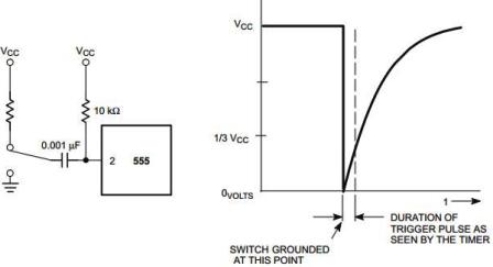
Figure 4
In general, a one-shot (sometimes called a single-shot, and the brave military had the word kipp relay in use) works as follows. When a button is pressed, a low level pulse at pin 2 causes the output of timer 3 to set a high level. For good reason, this signal (pin 2) in domestic directories is called a trigger.
The transistor connected to terminal 7 (DISCHARGE) is closed in this state. Therefore, nothing prevents charging the time-setting capacitor C. During the kipp relay, of course, there were no 555, everything was done on lamps, at best on discrete transistors, but the algorithm of operation was the same.
While the capacitor is charging, a high level voltage is maintained at the output. If at this time another pulse is applied to input 2, the state of the output will not change, the duration of the output pulse cannot be reduced or increased in this way, and the single-shot will not restart.
Another thing is if you apply a reset pulse (low level) to 4 pin. Output 3 will immediately display a low level. The “reset” signal has the highest priority, and therefore can be given at any time.
As the charge increases, the voltage across the capacitor increases, and, in the end, reaches the level of 2 / 3U. As described in a previous article, this is the response level, threshold, of the upper comparator, which leads to a reset of the timer, which is the end of the output pulse.
At pin 3, a low level appears and at the same moment the transistor VT3 opens, which discharges the capacitor C. This completes the pulse formation.If after the end of the output pulse, but not earlier, give another trigger pulse, then the output will be formed output, the same as the first.
Of course, for normal operation of a single-shot, the trigger pulse must be shorter than the pulse generated at the output.
Figure 5 shows a single vibrator schedule.

Figure 5. Single Vibrator Schedule
How can I use a single vibrator?
Or as the cat Matroskin used to say: “What will be the use of this one-shot?” It can be answered that it is big enough. The fact is that the range of time delays that can be obtained from this one-shot can reach not only a few milliseconds, but also reach several hours. It all depends on the parameters of the timing RC chain.
Here you are, almost ready-made solution for lighting a long corridor. It is enough to supplement the timer with an executive relay or a simple thyristor circuit, and put a couple of buttons at the ends of the corridor! He pressed the button, the corridor passed, and there was no need to worry about turning off the light bulb. Everything will happen automatically at the end of the time delay. Well, this is just information for consideration. Lighting in a long corridor, of course, is not the only option for using a single vibrator.
How to check 555?
The simplest way is to solder a simple circuit, for this there will be almost no need for hinged parts, except for the only variable resistor and LED to indicate the status of the output.
The microcircuit should connect pins 2 and 6 and apply voltage to them, changed by a variable resistor. You can connect a voltmeter or LED to the timer output, of course, with a limiting resistor.
But you can not solder anything, moreover, conduct experiments even with the “presence of absence” of the actual microcircuit. Similar studies can be done using the program-simulator Multisim. Of course, such a study is very primitive, but, nevertheless, it allows you to get acquainted with the logic of the 555 timer. The results of the "laboratory work" are shown in Figures 6, 7 and 8.

Figure 6
In this figure, you can see that the input voltage is regulated by a variable resistor R1. Near it, you can consider the inscription “Key = A”, which says that the resistor value can be changed by pressing the A key. The minimum adjustment step is 1%, it only saddens that regulation is possible only in the direction of increasing resistance, and reduction is possible only with the “mouse ".
In this figure, the resistor is "withdrawn" to the very "ground", the voltage on its motor is close to zero (for clarity, it is measured with a multimeter). With this position of the engine, the timer output is high, so the output transistor is closed, and LED1 does not light up, as its white arrows indicate.
The following figure shows that the voltage has increased slightly.

Figure 7
But the increase took place not just like that, but in compliance with certain boundaries, and, namely, the thresholds for the operation of comparators. The fact is that 1/3 and 2/3, expressed in decimal percentages, will be 33.33 ... and 66.66 ... respectively. It is in percentage that the input part of the variable resistor in the Multisim program is shown. With a 12V supply voltage, this will turn out to be 4 and 8 volts, which is convenient enough for research.
So, Figure 6 shows that the resistor is introduced at 65%, and the voltage on it is 7.8V, which is slightly less than the calculated 8 volts. In this case, the output LED is off, i.e. the timer output is still high.

Figure 8
A further slight increase in the voltage at inputs 2 and 6, by only 1 percent (the program does not allow less) leads to the ignition of the LED1, as shown in Figure 8, - the arrows near the LED acquired a red tint. This behavior of the circuit suggests that the Multisim simulator works quite accurately.
If you continue to increase the voltage at pins 2 and 6, then no change will occur at the output of the timer.
555 Timer Generators
The frequency range generated by the timer is quite wide: from the lowest frequency, the period of which can reach several hours, to frequencies of several tens of kilohertz. It all depends on the elements of the timing chain.
If a strictly rectangular waveform is not required, a frequency of up to several megahertz can be generated. Sometimes this is quite acceptable - the form is not important, but there are impulses. Most often, such negligence about the shape of the pulses is allowed in digital technology. For example, a pulse counter responds to a rising edge or falling pulse. Agree, in this case, the "squareness" of the pulse does not matter.
Square wave pulse generator
One of the possible variants of a meander-shaped pulse generator is shown in Figure 9.

Figure 9. Scheme of meander-shaped pulse generators
Timing diagrams of the generator are shown in Figure 10.

Figure 10. Timing diagrams of the generator
The upper graph illustrates the output signal (pin 3) of the timer. And the lower graph shows how the voltage across the time-setting capacitor changes.
Everything happens exactly as it was already considered in the single-vibrator circuit shown in Figure 3, but it does not use a single trigger pulse at pin 2.
The fact is that when the circuit on the capacitor C1 is turned on, the voltage is zero, it is it that will turn the timer output to a high level state, as shown in Figure 10. Capacitor C1 starts charging through resistor R1.
The voltage across the capacitor increases exponentially until it reaches the upper threshold threshold 2/3 * U. As a result, the timer switches to the zero state, therefore, the capacitor C1 starts to discharge to the lower threshold of operation 1/3 * U. Upon reaching this threshold, a high level is set at the output of the timer and everything starts all over again. A new period of oscillation is forming.
Here you should pay attention to the fact that the capacitor C1 is charged and discharged through the same resistor R1. Therefore, the charge and discharge times are equal, and, therefore, the form of oscillations at the output of such a generator is close to the meander.
The oscillation frequency of such a generator is described by a very complex formula f = 0.722 / (R1 * C1). If the resistance of the resistor R1 in the calculations is indicated in Ohms, and the capacitance of the capacitor is C1 in Farads, then the frequency will be in Hertz. If, in this formula, the resistance is expressed in kilo-ohms (KOhm), and the capacitance of the capacitor in microfarads (μF), the result will be in kilohertz (KHz). To get an oscillator with an adjustable frequency, it is enough to replace the resistor R1 with a variable.
Variable duty cycle pulse generator
The meander, of course, is good, but sometimes situations arise that require regulation of the duty cycle of the pulses. This is how the speed regulation of DC motors (PWM regulators), which are with a permanent magnet, is carried out.
Square wave pulses are called a meander, in which the pulse time (high level t1) is equal to the pause time (low level t2). Such a name in electronics came from architecture, where a meander is called a drawing of brickwork. The total pulse and pause times are called the pulse period (T = t1 + t2).
Duty and Duty Cycle
The ratio of the pulse period to its duration S = T / t1 is called the duty cycle. This value is dimensionless. In the meander, this indicator is 2, since t1 = t2 = 0.5 * T. In the English language literature, instead of the duty cycle, the reciprocal is often used, - duty cycle (Eng. Duty cycle) D = 1 / S, expressed as a percentage.
If you slightly improve the generator shown in Figure 9, you can get a generator with adjustable duty cycle. A diagram of such a generator is shown in Figure 11.
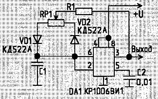
Figure 11.
In this scheme, the charge of the capacitor C1 occurs through the circuit R1, RP1, VD1.When the voltage across the capacitor reaches the upper threshold of 2/3 * U, the timer switches to the low level and capacitor C1 discharges through the circuit VD2, RP1, R1 until the voltage across the capacitor drops to the lower threshold of 1/3 * U, after whereby the cycle repeats.
Changing the position of the RP1 engine makes it possible to control the duration of the charge and discharge: if the duration of the charge increases, then the discharge time decreases. In this case, the pulse repetition period remains unchanged, only the duty cycle, or duty cycle, changes. Well, it’s more convenient for anyone.
Based on the 555 timer, you can design not only generators, but also many more useful devices, which will be discussed in the next article. By the way, there are programs - calculators for calculating the frequency of generators on the 555 timer, and in the program - the Multisim simulator there is a special tab for these purposes.
Boris Aladyshkin, https://env.electricianexp.com
Continuation of the article: 555 Integrated Timer. Traveling the Data sheet
See also at bgv.electricianexp.com
: