Categories: Featured Articles » Practical Electronics
Number of views: 10,626
Comments on the article: 1
Discrete Component Field Effect Transistor Driver
It's one thing when for high-speed control of a powerful field-effect transistor with a heavy gate there is ready-made driver in the form of a specialized chip like UCC37322, and quite different when there is no such driver, and the power key control scheme must be implemented here and now.
In such cases, it is often necessary to resort to the help of discrete electronic components that are available, and already from them to assemble the shutter driver. The case, it would seem, is not tricky, however, in order to obtain adequate time parameters for switching the field effect transistor, everything must be done efficiently and work correctly.
A very worthwhile, concise and high-quality idea with the goal of solving a similar problem was proposed back in 2009 by Sergey BSVi in his blog “Embedder Page”.
The circuit was successfully tested by the author in the half-bridge at frequencies up to 300 kHz. In particular, at a frequency of 200 kHz, with a load capacitance of 10 nF, it was possible to obtain fronts with a duration of no more than 100 ns. Let's look at the theoretical side of this solution, and try to understand in detail how this scheme works.
The main currents of the charge and discharge of the gate when unlocking and locking the master key flow through the bipolar transistors of the driver output stage. These transistors must withstand the peak gate control current, and their maximum collector-emitter voltage (according to the datasheet) must be greater than the driver supply voltage. Typically, 12 volts is enough to control the field shutter. As for the peak current, we assume that it does not exceed 3A.
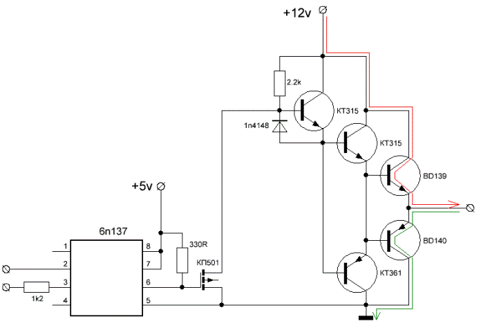
If a higher current is needed to control the key, then the transistors of the output stage must also be more powerful (of course, with a suitable limiting frequency of current transfer).
For our example, a complementary pair - BD139 (NPN) and BD140 (PNP) is suitable as transistors of the output stage. They have a collector-emitter limit voltage of 80 volts, a peak collector current of 3A, a cutoff current transfer frequency of 250 MHz (important!), And a minimum static current transfer coefficient of 40.
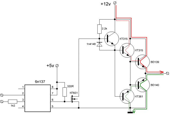
To increase the current gain, an additional complementary pair of low-current transistors KT315 and KT361 with a maximum reverse voltage of 20 volts, a minimum static current transfer coefficient of 50, and a cutoff frequency of 250 MHz is added as high as the output transistors BD139 and BD140 .
As a result, we get two pairs of transistors connected according to the Darlington circuit with a total minimum current transfer coefficient of 50 * 40 = 2000 and with a cutoff frequency of 250 MHz, that is, theoretically in the limit, the switching speed can reach several nanoseconds. But since we are talking about relatively long processes of charge and discharge of the gate capacitance, this time will be an order of magnitude higher.
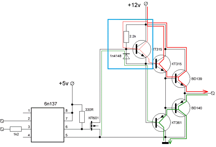
The control signal must be supplied to the combined base of transistors KT315 and KT361. The opening currents of the bases NPN (upper) and PNP (lower) transistors must be separated.
For this purpose, isolation resistors could be installed in the circuit, but the solution with the installation of an auxiliary unit on the KT315, resistor and 1n4148 diode turned out to be much more effective for this particular circuit.
The function of this unit is to quickly activate the base of the upper transistors of the low-current stage when applying a higher voltage to the base of this unit, and just as quickly through the diode pull the bases to minus when a signal of the lowest level appears on the base of the unit.
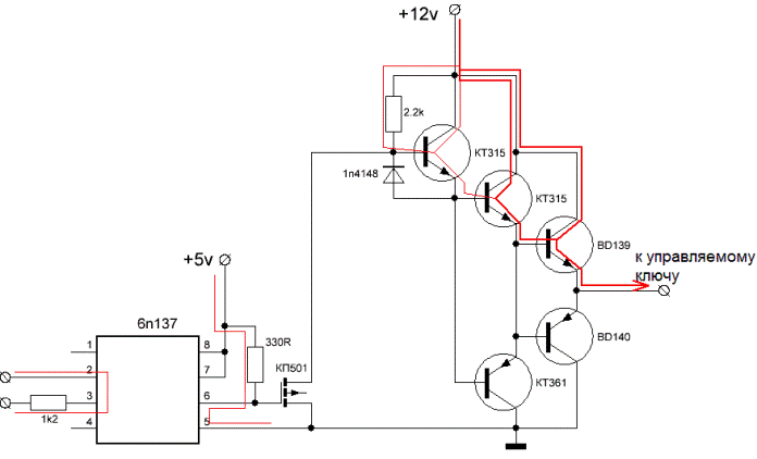
In order to be able to control this driver from a low-current signal source with an output current of the order of 10 mA, a low-current field-effect transistor KP501 and a high-speed optocoupler 6n137 are installed in the circuit.
When a control current is applied through a chain of 2-3 optocouplers, the output bipolar transistor inside it goes into a conducting state, and at pin 6 there is an open collector to which a resistor is connected, which pulls the gate of the low-current field-effect transistor KP501 to the positive power bus of the optocoupler.
Thus, when a high level signal is supplied to the input of the optocoupler, a low level signal will be on the gate of the KP501 field controller, and it will close, thereby providing the possibility for current to flow through the base of the upper one according to the KT315 scheme - the driver will charge the gate of the main field controller.
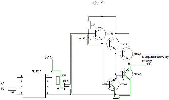
If at the input of the optocoupler there is a low level signal or there is no signal, then at the output of the optocoupler there will be a high level signal, the KP501 shutter will charge, its stock circuit will close, and the base of the upper circuit according to the KT315 circuit will be pulled to zero.
The driver output stage will begin to discharge the gate of the key it controls. It is important to note that in this example the power supply voltage of the optocoupler is limited to 5 volts, and the main stage of the driver is powered by a voltage of 12 volts.
See also at i.electricianexp.com
:
