Categories: Featured Articles » Practical Electronics
Number of views: 15595
Comments on the article: 0
Quick assembly of circuits on solderless breadboards
Let's look at the design and purpose of solderless breadboards. What is their advantage over other types of assembly, and how to work with them, as well as what schemes you can quickly assemble for a beginner.
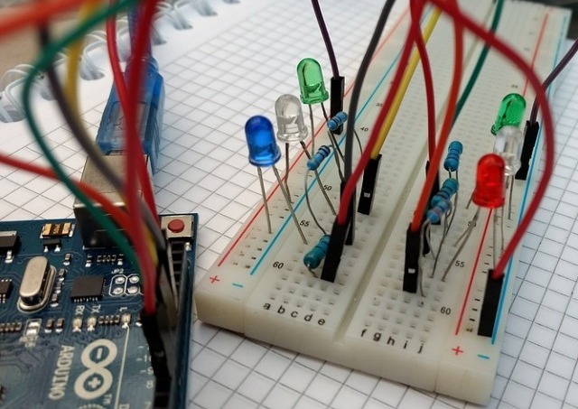
Background
The first problem that a radio amateur faces is not even the lack of theoretical knowledge, but the lack of means and knowledge about how to install electronic devices. If you don’t know how this or that part works, this will not stop you from connecting it according to the circuit diagram, but in order to clearly and efficiently assemble the circuit, you need a printed circuit board. Most often they are made using the LUT method, but not everyone has a laser printer. Our fathers and grandfathers painted boards manually with nail polish or paint, and then they were etched.
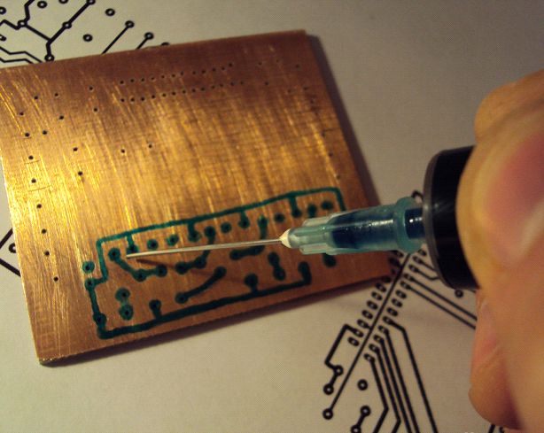
Here the novice is overtaken by a second problem - the lack of etching reagents. Yes, of course, ferric chloride is sold in every store of electronic components, but at first you need to buy and study a lot of things, so it is simply difficult to pay attention to the etching technology of boards made of foil-coated textolite or getinaks. Yes, and not only for beginners, but also for experienced radio amateurs, it sometimes makes no sense to poison the board and spend money on an unfinished product at the stages of its commissioning.
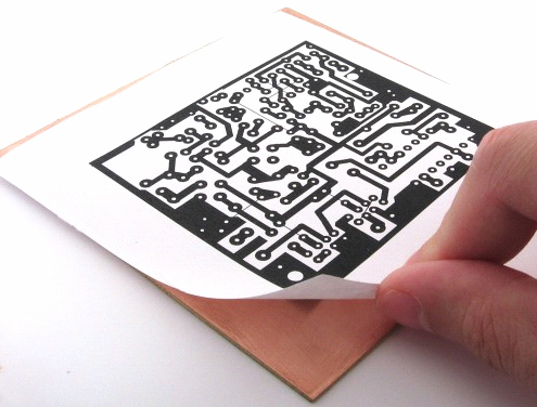
In order to avoid problems with the search for ferric chloride, PCB, printer, and not to get from his wife (mother) for unauthorized use of the iron, you can practice installing electronic devices on solderless breadboards.
What is a solderless breadboard?
As the name implies, this is such a board on which you can assemble the device’s layout without using a soldering iron. The breadboard model - as it is popularly called - in stores there are different sizes and models are somewhat different in layout, but the principle of operation and their internal structure are the same.
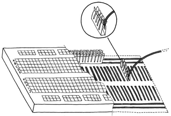
The breadboard consists of a housing made of ABS plastic, in which are detachable connections that resemble dual metal tires between which the conductor is clamped. On the front of the case, the holes are numbered and marked, you can insert wires, legs of the microcircuit, transistors and other radio components in the cases with leads. Take a look at the picture below, on it I depicted all this.
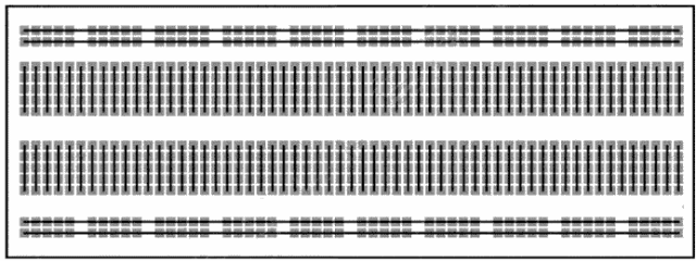
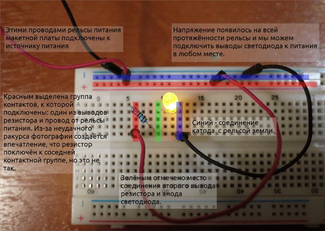
On the considered printed circuit board, the extreme two columns of holes on each side are vertically connected by common buses, from which the bus of the positive contact of the power supply and the negative (common bus) are usually formed. Usually indicated by a red and blue stripe along the edge of the board, plus and minus, respectively.
The middle part of the board is divided into two parts, each of the parts are combined in rows of five holes in a row on this particular board. The figure shows a schematic connection of holes (solid black lines).
The internal structure of the board is shown in the figure below. Dual busbars clamp the conductors, which is illustrated. Bold lines indicate internal connections.
Such boards in the English language environment are called Breadboard by this name, you can find it on aliexpress and similar online stores.
How to work with her?
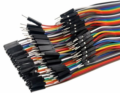
Just insert the legs of the electronic components into the holes, connecting the parts together in horizontal lines, and from the extreme verticals, supply power. If you need a jumper, you often use special ones with thin plugs at the end, in stores you can find them under the name "dupont jumpers" or jumpers for arduino, by the way, you can also insert it into such a breadboard and collect your projects.
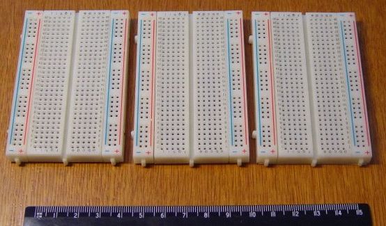
If you didn’t have enough sizes of one breadboard, you can combine several, it is like puzzles inserted into each other, pay attention to the first picture in the article, the circuit is assembled on two connected boards. On one of them there is a spike, and on the other there is a recess, beveled from the outer part to the board case, so that the structure does not fall apart.
Assembling simple circuits on a breadboard
It is important for a beginner radio amateur to quickly assemble a circuit to make sure that it works and understand how it works. Let's look at how different schemes look on a breadboard.
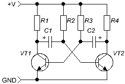
The symmetric multivibrator circuit is recommended as the first for many beginners, it allows you to learn how to connect parts in series and in parallel, and also to determine the wiring of transistors. It can be assembled by wall mounting or a PCB, but this requires soldering, and wall mounting, despite its simplicity, is actually very difficult for beginners and is fraught with short circuits or poor contact.
See how simple it looks on a solderless breadboard.
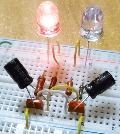
By the way, pay attention here Dupont jumpers were not used. In general, they can not always be found in radio stores, and especially in shops in small towns. Instead, you can use the wires from the Internet cable (Twisted pair), they are isolated, and the core is not varnished, which allows you to quickly expose the end of the cable, removing a small layer of insulation and insert it into the connector on the board.
You can connect the parts as you like, just to provide the desired circuit, here is the same circuit, but assembled slightly differently.
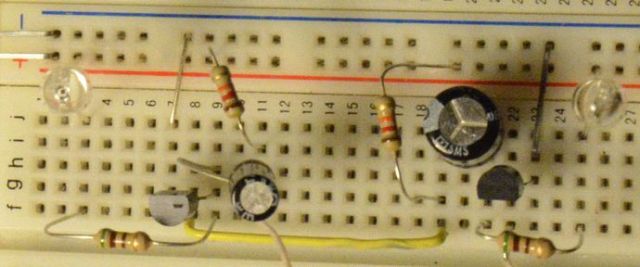
By the way, to describe the connections, you can use the marking of the board, the columns are indicated by letters, and the rows by numbers.
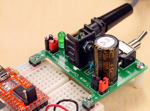
For your designs, there are such power supplies, they have plugs that are mounted in a solderless board by connecting to the "+" and "-" buses. It is convenient, it has a switch and a linear low-noise voltage regulator. In general, it will not be difficult for you to breed such a fee yourself and collect it.
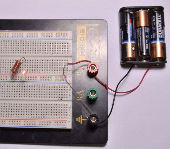
Like this can connect LED, for example, to check it. The picture shows a more “advanced” version of the circuit board with clamping terminals for connecting a power source. The anode of the LED is connected to the power plus (red bus) and the cathode to the horizontal bus of the working area, where it is connected to a current-limiting resistor.
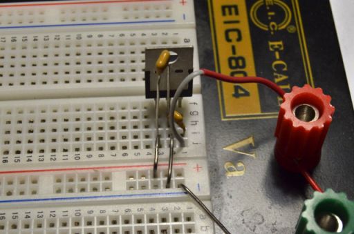
The power supply is based on a linear stabilizer such as L7805, or any other chip in the L78xx series, where xx is the voltage you need.
Assembled scheme tweeters on the logic. The correct name for such a circuit is a Pulse Generator on logic elements of the 2i-ne type. First, familiarize yourself with the electrical circuit diagram.
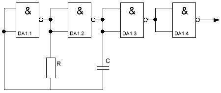
As a logical microcircuit, a domestic K155LA3 or a foreign type 74HC00 is suitable. Elements R and C set the operating frequency. Here is its implementation on the board without soldering.
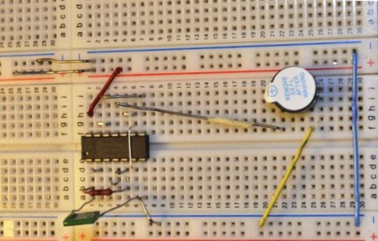
To the right, sealed with white paper - buzzer. It can be replaced by an LED if the frequency is reduced.
The greater the Resistance OR capacity, the lower the frequency.
And here is what a typical project of Arduinchik looks like at the testing and development stage (and sometimes in the final form, it depends on how lazy he is).
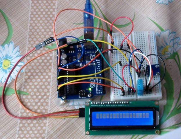
Actually thanks to the Arduino project in recent years, the popularity of "crazy" has increased significantly. They allow you to quickly assemble circuits and check their performance, as well as use as a connector for flashing chips in the DIP package, and in other cases, if there is an adapter.
Limitations of the solderless breadboard
Despite its simplicity and obvious advantages over soldering, solderless breadboards have several disadvantages. The fact is that not all circuits work normally in such a design, let's take a closer look.
Overload and spurious components
On solderless breadboards, it is not recommended to assemble powerful converters, and especially pulse circuits. The former will not work normally due to the current throughput of the contact tracks.Do not climb over currents of more than 1-2 Amperes, although there are reports on the Internet that include 5 Amperes, draw your own conclusions and experiment.
Pulse circuits may not work at all due to the large number of stray capacitances and inductances in the circuit. The location of the tires is such that they run along each other and have a fairly large area. This causes unnecessary interference and does not improve the stability of the pulse and precision circuits.
electrical safety
Do not forget that high voltage is life threatening. Prototyping devices operating, for example from 220 V is FORBIDDEN categorically. Although the terminals are covered with a plastic panel, a bunch of conductors and jumpers can lead to accidental short circuit or electric shock!
Conclusion
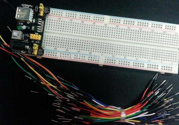
The solderless breadboard is suitable for simple circuits, analog circuits that do not have high requirements for electrical connections and accuracy, automation and digital circuits that do not work at high speeds (Gigahertz and dozens of Megahertz are too much). At the same time, high voltage and currents are dangerous and for such purposes it is better to use hinged installation and printed circuit boards, while a beginner should not make hinged installation of such circuits. The element of solderless prototyping boards is the simplest circuits of up to a dozen elements and amateur projects on Arduino and other microcontrollers.
See also at i.electricianexp.com
:
