Categories: Practical Electronics, All about LEDs
Number of views: 445777
Comments on the article: 28
Good and bad LED wiring patterns
In previous articles, various issues related to connecting LEDs have been described. But you cannot write everything in one article, so you have to continue this topic. Here we will talk about various ways to turn on the LEDs.
As mentioned in the mentioned articles, LED is a current device, i.e. the current through it must be limited by a resistor. How to calculate this resistor has already been described, we will not repeat here, but we will give the formula, just in case, again.

Picture 1.
Here is up. - supply voltage, Uad. - voltage drop across the LED, R - resistance of the limiting resistor, I - current through the LED.
However, despite all the theory, the Chinese industry produces all kinds of souvenirs, trinkets, lighters, in which the LED is turned on without a limiting resistor: just two or three disk batteries and one LED. In this case, the current is limited by the internal resistance of the battery, the power of which is simply not enough to burn the LED.
But here, in addition to burnout, there is another unpleasant property - the degradation of LEDs, most inherent in white and blue LEDs: after a while, the brightness of the glow becomes quite insignificant, although the current through the LED flows quite enough, at the nominal level.
This is not to say that it does not shine at all, the glow is barely noticeable, but this is no longer a flashlight. If at rated current degradation occurs no earlier than after a year of continuous luminescence, then at high current, this phenomenon can be expected in half an hour. This inclusion of the LED should be called bad.
Such a scheme can only be explained by the desire to save on one resistor, solder, and labor costs, which, with a massive scale of production, is apparently justified. In addition, a lighter or keychain is a one-time, cheap thing: the gas has run out or the battery has run out - they simply threw away the souvenir.
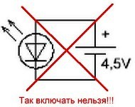
Figure 2. The scheme is bad, but it is used quite often.
Very interesting things come out (of course, by accident) if, by such a scheme, the LED is connected to a power supply unit with an output voltage of 12V and a current of at least 3A: a dazzling flash occurs, a fairly loud pop, smoke is heard, and a suffocating smell remains. So I recall this parable: “Is it possible to look at the Sun through a telescope? Yes, but only twice. Once with the left eye, the other with the right. ” By the way, connecting an LED without a limiting resistor is the most common mistake among beginners, and I would like to warn about it.
To correct this situation, extend the life of the LED, the circuit should be slightly modified.

Figure 3. Good layout, correct.
It is such a scheme that should be considered good or correct. To check whether the value of the resistor R1 is correctly indicated, you can use the formula shown in Figure 1. We assume that the voltage drop on the LED 2V, current 20mA, voltage 3V due to the use of two finger batteries.
In general, one does not have to strive to limit the current to the level of maximum permissible 20 mA, you can power the LED with a lower current, well, at least, a milliamp 15 ... 18. In this case, there will be a very slight decrease in brightness, which the human eye, due to the characteristics of the device, will not notice at all, but the life of the LED will increase significantly.
Another example of poorly turned on LEDs can be found in various flashlights, already more powerful than key rings and lighters. In this case, a certain number of LEDs, sometimes quite large, are simply connected in parallel, and also without a limiting resistor, which again acts as the internal resistance of the battery.Such flashlights quite often get into repair precisely because of the burnout of the LEDs.

Figure 4. Absolutely bad wiring diagram.
It would seem that the situation shown in Figure 5 can correct the situation. Just one resistor, and, it would seem, things got better.

Figure 5. This is already a little better.
But such an inclusion will help a little. The fact is that in nature it is simply not possible to find two identical semiconductor devices. That is why, for example, transistors of the same type have different gain, even if they are from the same production batch. Thyristors and triacs are also different. Some open easily, while others are so heavy that they have to be abandoned. The same can be said about the LEDs - two absolutely identical, especially three or a whole bunch, it is simply impossible to find.
Note on the topic. In the DataSheet for the SMD-5050 LED assembly (three independent LEDs in one housing), the inclusion shown in Figure 5 is not recommended. Like, due to the scatter of the parameters of individual LEDs, the difference in their glow may be noticeable. And it would seem, in one case!
LEDs, of course, have no gain, but there is such an important parameter as a direct voltage drop. And even if the LEDs are taken from one technological batch, from one package, then there will simply not be two identical ones in it. Therefore, the current for all LEDs will be different. That LED, in which the current will be the most, and sooner or later will exceed the nominal, will light up before everyone else.
In connection with this unfortunate event, all possible current will go through the two surviving LEDs, naturally exceeding the nominal one. After all, the resistor was calculated "for three", for three LEDs. An increased current will cause an increased heating of the LED crystals, and one that is “weaker” also burns out. The last LED also has no choice but to follow the example of its comrades. Such a chain reaction is obtained.
In this case, the word "burn" means simply breaking the circuit. But it can happen that in one of the LEDs an elementary short circuit will result, shunting the remaining two LEDs. Naturally, they will surely go out, although they will survive. With such a malfunction, the resistor will heat up intensely and, in the end, it may burn out.
To prevent this from happening, the circuit needs to be slightly changed: for each LED, install its own resistor, which is shown in Figure 6.
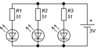
Figure 6. And so, the LEDs will last a very long time.
Here, everything is as required, all according to the rules of circuit design: the current of each LED will be limited by its resistor. In such a circuit, the currents through the LEDs are independent of each other.
But this inclusion does not cause much enthusiasm, since the number of resistors is equal to the number of LEDs. But I would like to have more LEDs, and fewer resistors. How to be?
The way out of this situation is quite simple. Each LED must be replaced by a chain of series-connected LEDs, as shown in Figure 7.
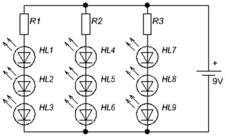
Figure 7. Parallel inclusion of garlands.
The cost of such an improvement will be an increase in the supply voltage. If only one volt is enough for one LED, then even two LEDs connected in series cannot be ignited from such voltage. So what voltage is needed to turn on a garland of LEDs? Or in another way, how many LEDs can be connected to a power source with a voltage, for example, 12V?
Comment. Hereinafter, the term “garland” should be understood not only as a Christmas tree decoration, but also as any lighting LED device in which the LEDs are connected in series or in parallel. The main thing is that there is more than one LED. A garland, it is also a garland in Africa!
To get an answer to this question, it is enough to simply divide the supply voltage by the voltage drop on the LED. In most cases, when calculating this voltage is taken 2V. Then it turns out 12/2 = 6.But do not forget that some part of the voltage must remain for the quenching resistor, at least volt 2.
It turns out that only 10V remains on the LEDs, and the number of LEDs becomes 10/2 = 5. In this situation, in order to obtain a current of 20 mA, the limiting resistor must have a nominal value of 2V / 20mA = 100Ohm. The power of the resistor will be P = U * I = 2V * 20mA = 40mW.
Such a calculation is quite true if the forward voltage of the LEDs in the garland, as indicated, is 2V. It is this value that is often taken in the calculations, as some average. But in fact, this voltage depends on the type of LEDs, on the color of the glow. Therefore, when calculating the daisies, you should focus on the type of LEDs. Voltage drops for different types of LEDs are shown in the table shown in Figure 8.

Figure 8. Voltage drop on LEDs of different colors.
Thus, with a 12V power supply voltage, minus the voltage drop across the current-limiting resistor, a total of 10 / 3.7 = 2.7027 white LEDs can be connected. But you can’t cut off a piece of the LED, so only two LEDs can be connected. This result is obtained if we take the maximum value of the voltage drop from the table.
If we substitute 3V into the calculation, then it is obvious that three LEDs can be connected. In this case, each time you have to painstakingly count the resistance of the limiting resistor. If real LEDs turn out to have a voltage drop of 3.7V, or maybe higher, the three LEDs may not light up. So it’s better to stop at two.
It doesn’t fundamentally matter what color the LEDs will be, just when calculating you will have to take into account different voltage drops depending on the color of the LEDs. The main thing is that they are designed for one current. It is impossible to assemble a consistent garland of LEDs, some of which have a current of 20 mA, and the other part of 10 milliamps.
It is clear that at a current of 20 mA, LEDs with a rated current of 10 mA will simply burn out. If you limit the current to 10 mA, then 20 milliamperes will not light up brightly, like in a switch with an LED: you can see at night, not in the afternoon.
To make life easier for themselves, radio amateurs develop various calculator programs that facilitate all kinds of routine calculations. For example, programs for calculating inductances, filters of various types, current stabilizers. There is such a program for calculating LED garlands. A screenshot of such a program is shown in Figure 9.

Figure 9. Screenshot of the program “Calculation_resistance_resistor_Ledz_”.
The program works without installation in the system, you just need to download and use it. Everything is so simple and clear that no explanation for the screenshot is required at all. Naturally, all LEDs must be of the same color and with the same current.
See also from a previously published on the site: How to connect the LED to the lighting network
Limit resistors are, of course, good. But only when it is known that this garland will be powered by stabilized source DC 12V, and the current through the LEDs will not exceed the calculated value. But what if there is simply no source with a voltage of 12V?
Such a situation may arise, for example, in a truck with a voltage of 24V on-board network. To get out of such a crisis situation, a current stabilizer will help, for example, “SSC0018 - Adjustable current stabilizer 20..600mA”. Its appearance is shown in Figure 10. Such a device can be bought in online stores. The price of the issue is 140 ... 300 rubles: it all depends on the imagination and arrogance of the seller.

Figure 10. Adjustable Current Regulator SSC0018
The stabilizer specifications are shown in Figure 11.
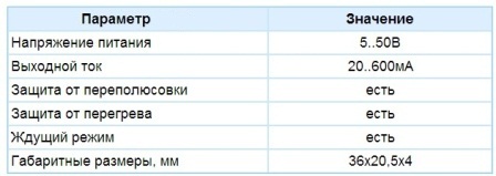
Figure 11. Technical characteristics of the current stabilizer SSC0018
Initially, the SSC0018 current stabilizer was designed for use in LED lighting fixtures, but can also be used to charge small batteries. Using the SSC0018 is quite simple.
The load resistance at the output of the current stabilizer can be zero, you can simply short-circuit the output terminals. After all, stabilizers and current sources are not afraid of short circuits. In this case, the output current will be rated. Well, if you set 20mA, then so much will be.
From the foregoing, we can conclude that a milliammeter of direct current can be directly connected to the output of the current stabilizer. Such a connection should be started from the largest measurement limit, because no one knows what current is regulated there. Next, simply rotate the tuning resistor to set the required current. In this case, of course, do not forget to connect the current stabilizer SSC0018 to the power supply. Figure 12 shows the SSC0018 wiring diagram for powering LEDs connected in parallel.
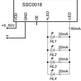
Figure 12. Connection for powering LEDs connected in parallel
Everything here is clear from the diagram. For four LEDs with a consumption current of 20 mA, each output of the stabilizer must be set to a current of 80 mA. In this case, at the input of the stabilizer SSC0018, a little more voltage is required than the voltage drop on one LED, as mentioned above. Of course, a larger voltage is suitable, but this will only lead to additional heating of the stabilizer chip.
Comment. If, to limit the current with a resistor, the voltage of the power source should slightly exceed the total voltage at the LEDs, only two volts, then for the normal operation of the current stabilizer SSC0018 this excess should be slightly higher. No less than 3 ... 4V, otherwise the regulating element of the stabilizer simply will not open.
Figure 13 shows the connection of the SSC0018 stabilizer when using a garland of several series-connected LEDs.

Figure 13. Powering a Serial String through the SSC0018 Stabilizer
The figure is taken from the technical documentation, so let's try to calculate the number of LEDs in the garland and the constant voltage required from the power supply.
The current indicated on the diagram, 350mA, allows us to conclude that the garland is assembled from powerful white LEDs, because, as mentioned above, the main purpose of the SSC0018 stabilizer is lighting sources. The voltage drop across the white LED is within 3 ... 3.7V. For the calculation, you should take the maximum value of 3.7V.
The maximum input voltage of the stabilizer SSC0018 is 50V. Subtract from this value of 5V, necessary for the stabilizer itself, remains 45V. This voltage can be "illuminated" 45 / 3.7 = 12.1621621 ... LEDs. Obviously, this should be rounded to 12.
The number of LEDs may be less. Then the input voltage will have to be reduced (while the output current will not change, it will remain 350mA as it was adjusted), why should I supply 50V to 3 LEDs, even powerful ones? Such mockery can end in failure, because powerful LEDs are by no means cheap. What voltage will be required to connect three powerful LEDs for those who want, but they can always be found, they can calculate for themselves.
Adjustable current stabilizer SSC0018 device is quite good. But the whole question is, is it always needed? And the price of the device is somewhat confusing. What can be the way out of this situation? Everything is very simple. An excellent current regulator is obtained from integrated voltage stabilizers, for example, the 78XX or LM317 series.
To create such a current stabilizer based on a voltage stabilizer, only 2 parts are required. Actually the stabilizer itself and one single resistor, the resistance and power of which will help to calculate the StabDesign program, a screenshot of which is shown in Figure 14.
Picture 14. The calculation of the current stabilizer using the program StabDesign.
The program does not require special explanations. In the Type drop-down menu, the type of stabilizer is selected, in the line Iн the required current is set and the Calculate button is pressed. The result is the resistance of the resistor R1 and its power. In the figure, the calculation was performed for a current of 20 mA.This is the case when the LEDs are connected in series. For a parallel connection, the current is calculated in the same way as shown in Figure 12.
The LED garland is connected instead of the resistor Rн, symbolizing the load of the current stabilizer. It is even possible to connect just one LED. In this case, the cathode is connected to a common wire, and the anode to resistor R1.
The input voltage of the considered current stabilizer is in the range of 15 ... 39V, since the stabilizer 7812 with a stabilization voltage of 12V is used.
It would seem that this is the end of the story about LEDs. But there are also LED strips, which will be discussed in the next article.
Continuation of the article: LED strip application
Boris Aladyshkin
See also at bgv.electricianexp.com
:

