Categories: Practical Electronics, Electrician Secrets
Number of views: 303,358
Comments on the article: 25

How to make a simple current regulator for a welding transformer
 

How to make a simple current regulator for a welding transformerAn important design feature of any welding machine is the ability to adjust the operating current. In industrial apparatuses, different methods of adjusting the current are used: shunting with various types of chokes, changing the magnetic flux due to the mobility of the windings or magnetic shunting, using active ballast resistances and rheostats. The disadvantages of this adjustment include the complexity of the design, the bulkiness of the resistances, their strong heating during operation, inconvenience when switching.

The most optimal option - even when winding the secondary winding, make it with taps and, by switching the number of turns, change the current. However, this method can be used to adjust the current, but not to adjust it over a wide range. In addition, the regulation of the current in the secondary circuit of the welding transformer is associated with certain problems.

So, significant currents pass through the control device, which leads to its cumbersomeness, and it is almost impossible to select such powerful standard switches for the secondary circuit that they can withstand currents up to 200 A. Another thing is the primary winding circuit, where the currents are five times less.

After a long search through trial and error, the optimal solution to the problem was found - the well-known thyristor regulator, the circuit of which is shown in Fig. 1.
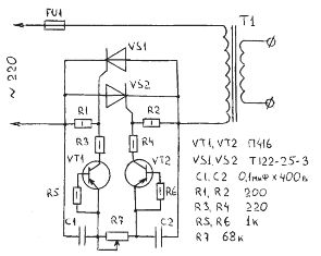
Welding current regulator circuit

With the utmost simplicity and accessibility of the element base, it is easy to manage, requires no settings, and has proven itself in work - it works just like a "clock".

Power regulation occurs when the primary winding of the welding transformer is periodically disconnected for a fixed period of time at each half-period of the current. The average current value decreases.

The main elements of the regulator (thyristors) are turned on and parallel to each other. They are alternately opened by current pulses generated by transistors VT1, VT2. When the regulator is connected to the network, both thyristors are closed, the capacitors C1 and C2 begin to charge through the variable resistor R7. As soon as the voltage on one of the capacitors reaches the avalanche breakdown voltage of the transistor, the latter opens, and the discharge current of the capacitor connected to it flows through it.
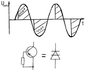
Welding current regulator circuit

Following the transistor, the corresponding thyristor opens, which connects the load to the network. After the start of the next alternating current half-cycle alternating current sign, the thyristor closes and a new cycle of charging capacitors begins, but in reverse polarity. Now the second transistor opens, and the second thyristor connects the load to the network again.

By changing the resistance of the variable resistor R7, it is possible to regulate the moment the thyristors are turned on from the beginning to the end of the half-cycle, which in turn leads to a change in the total current in the primary winding of the welding transformer T1. To increase or decrease the adjustment range, you can change the resistance of the variable resistor R7 up or down, respectively.

Transistors VT1, VT2 operating in the avalanche mode, and resistors R5, R6 included in their base circuits, can be replaced with dynistors. The anodes of the dinistors should be connected to the extreme terminals of the resistor R7, and the cathodes should be connected to the resistors R3 and R4. If the regulator is assembled on dinistors, then it is better to use devices such as KN102A.

As VT1, VT2, transistors of the old type P416, GT308 type have proven themselves well. It is quite realistic to replace them with more modern low-power high-frequency ones that have similar parameters.

Variable resistor type SP-2, the rest type MLT. Capacitors like MBM or MBT for a working voltage of at least 400 V.
How to make a simple current regulator for a welding transformer

A properly assembled regulator does not require adjustment. You just need to make sure stable operation of transistors in avalanche mode (or in the stable inclusion of dinistors).

Attention! The device has galvanic connection to the network. All elements, including thyristor heatsinks, must be isolated from the housing.

See also on the topic: Thyristor Power Regulators andHome-made spot welding machines for the home workshop 

See also at i.electricianexp.com:

  • Homemade dimmers. Part Five Some more simple schemes
  • A simple home-made welding machine from LATR
  • Methods and circuits for controlling a thyristor or triac
  • Transformers and autotransformers - what is the difference and feature
  • Spot welding in the home workshop

  •  
     
    Comments:

    # 1 wrote: | [quote]


    This regulator does not work.

     
    Comments:

    # 2 wrote: Kolesiknn | [quote]


    Assembled this scheme. I tried on a DC device. When adjusting with a resistor, the transformer starts to buzz, in the extreme position, the trans starts to buzz and heat up, the machine in the shield cuts out after 10-15 seconds. So this scheme is not suitable for adjustment.

     
    Comments:

    # 3 wrote: Gene | [quote]


    Thanks guys!! For the warning !!

     
    Comments:

    # 4 wrote: Shaman | [quote]


    I collected it, for an active load, like incandescent lamps, TEN-s of heating, etc. The circuit is excellent, I have not tried it yet for trance, but I’m sure that the problems will be, but it’s thought to be solved, when the sine wave is cut off in thyristor-triac control primary due to a change in the shape of the supply voltage, the current increase is close to pulse, which leads to not weak emissions of self-induction EMF and the “wrong” magnetization reversal. In trance of low power, this was decided by selecting capacitors at the input of the primary, slightly smoothing the "irregular" form of the supply voltage, here I will experiment the same, but the trance for which I did the regulation is not finished yet, there is not enough time, so I can not publish the results before the summer)) For those who want a good adjustment with the predicted result for the welder, it is better to collect a time-tested circuit with thyristors for the secondary, from the same "Radio" for example. It will work like a clock, but konesh thyristors will have to be bought more powerful = (But it's worth it.

     
    Comments:

    # 5 wrote: | [quote]


    And where is the diode bridge?) If the world does not turn over, then the thyristors operate on direct current. I read your post and there are no mention of triacs operating on alternating current.

     
    Comments:

    # 6 wrote: Sergei | [quote]


    maybe the hands are not so sharpened? collected ! everything works fine (the only thing that did not find sp 2, put sp 3 and they are not enough for a long time ((

     
    Comments:

    # 7 wrote: | [quote]


    and for a beginner 17-year-old welder can it be somehow easier to draw a drawing ??? if so, please drop a mail

     
    Comments:

    # 8 wrote: | [quote]


    Old famous scheme. For a long time I have been collecting regulators for chargers, welders and lighting on it, but only on P416. It works flawlessly. In parallel, it is useful for thyristors to supply an RS chain of 100 ohms and 0.25-1 microfarads. For transformer especially. A secondary resistance load 50-150mA.

     
    Comments:

    # 9 wrote: | [quote]


    This regulator is not working !!!!!

     
    Comments:

    # 10 wrote: | [quote]


    Is it possible to replace the circuit with an electric drill rotation control circuit with replacing the thyristor with a more powerful one?

     
    Comments:

    # 11 wrote: | [quote]


    DrSMERTb,
    Is it okay that each thyristor with its half-wave works?

     
    Comments:

    # 12 wrote: | [quote]


    I made this circuit, checked it on a light bulb, everything works. Installed on the welding machine, it turns on, but before the first attempt to create an arc, the fuse is 3 (after and 5) A "into the dust." Tell me what kind of fuse should be (because it is not indicated in the diagram and description). It’s ridiculous to experiment yourself, because the scheme / money / time is a pity (in case the scheme burns out).

    Thanks in advance.

     
    Comments:

    # 13 wrote: | [quote]


    Valery,
    Additional information, I use a 16A automatic machine as a welding switch. In this case, can the fuse be excluded from the circuit?

     
    Comments:

    # 14 wrote: | [quote]


    I did not wait for your answers and connected directly ... all the rules, do not burn anything. Regulates the welding machine properly.

     
    Comments:

    # 15 wrote: | [quote]


    the circuit does not work as it is. I remove the wires of the control electrodes of the tiristra and it starts to work on giving a current of 200V!

     
    Comments:

    # 16 wrote: | [quote]


    Please answer my question -
    The regulator is working! Works great! But there is one “but”, when idling, it really lowers the voltage on my semiautomatic device, but as soon as I press the button on the burner, the voltage rises back, why?

     
    Comments:

    # 17 wrote: | [quote]


    INTERESTING SCHEME I WILL TRY TO ASSEMBLY! I WOULD LIKE TO SEE A SIMILAR SCHEME ON A SYMISTOR! THANKS TO THE AUTHOR !!!

     
    Comments:

    # 18 wrote: | [quote]


    This circuit is not working.

     
    Comments:

    # 19 wrote: Alexander | [quote]


    Assembled checked on a light bulb works, but from a welding transformer such an overload on the network you will not wish to the enemy.

     
    Comments:

    # 20 wrote: | [quote]


    This regulator is designed to operate only with active loads such as incandescent lamps or electric heating elements. The essence of overheating the transformer and increasing the current consumption is as follows: as can be seen from the voltage diagram, the leading edge, i.e. inclusion, can be considered as part of a rectangular pulse. From which it follows that in such an impulse there are higher harmonics. When switching at a frequency of 100 Hz, the highest harmonic is 1 kHz. Electrotechnical iron of welding transformers provides operation at frequencies of 50 - 60 Hz. At higher frequencies, losses sharply increase which lead to an increase in switching currents and, as a result, overheating of the transformer.

     
    Comments:

    # 21 wrote: | [quote]


    I assembled the circuit, it seems that the person is working, I did not test, but instead of p416 I installed CT 361, but I think it will be necessary to refine it a bit.

     
    Comments:

    # 22 wrote: | [quote]


    Excuse me, is this a working scheme or not ???? And then I want to collect for my homemade welder. There is no time to experiment.

     
    Comments:

    # 23 wrote: | [quote]


    If in parallel to the thyristors we put a wire resistance of the order of 2-4 ohms and a power of 50 watts, then we’ll go to a welder ... and in working with a trans, you need to select both thyristors (by sensitivity) and diodes by the switching voltage. I redid the seven options until I came to this conclusion. And so, the circuit is good, but not for inductive load.

     
    Comments:

    # 24 wrote: goose | [quote]


    let the author of the circuit put the soldered circuit in one place, when you turn the resistor slider, the current jumps immediately to the maximum. On one page was half of this scheme for starting electric motors, no use. Why crap all sorts of crap?

     
    Comments:

    # 25 wrote: Sergey Zavyalov | [quote]


    I assembled this circuit - it worked right away, but as already mentioned only on heating devices, but it doesn’t work normally on trans, I even assembled a similar circuit on the triac - the result is the same.