Categories: Sharing experience, About electricians and not only, Industrial electrician
Number of views: 31652
Comments on the article: 4
Modernization of the valve drive or the reversal of the capacitor motor. Workdays of the instrumentation and automation group
 Probably everyone saw the usual mechanical valve. It is enough in any courtyard of an apartment building to look at the heating main to see at least two gate valves at once.
Even without going into much of their design, and having no higher technical education, it is easy to understand that if you turn the handwheel, a shutter moves inside the pipe, which blocks the flow of water. It is from this that such a mechanism of pipe-and-valve valves “moves” and is called the “valve”. The device of a small mechanical valve is shown in Figure 1.
The use of such "manual" valves is justified only in those cases when the valve is used very rarely, from case to case, and their number is small. For example, block the pipeline section in the event of an accident. Well, a distribution pipe or riser flowed somewhere in the basement of the house!
When the valve is an element of the technological process, it has to be used often (several times per hour, or even more often), and the number of valves is in the tens, or even hundreds, electric valves are used.
Waterworks in a small town just have so many valves. Almost all of them are mechanized, controlled by a simple push of a button, or from a controller of a water supply automation system.

Figure 1. Mechanical shutter device
As a rule, an electric three-phase motor is used in the valve’s electric drive, the power and type of which is determined by the diameter of the pipe (100 ... 800 mm, and maybe more), on which the valve is installed: the larger the pipe’s diameter, the higher its chances of receiving the honorary title of a water conduit.
But then one day I had to install an electrified valve in the water pipe with a diameter of 400 mm instead of the old one, which had become unusable. And here confusion happened, but first things first.

Figure 2. Gearbox with engine.
The valve itself, of course, is in the well, the figure shows only the engine assembly with the gearbox. A black plastic box on top of the engine hides underneath terminal block for connecting wires. It was assumed that there was nothing more than the screws to connect there: as usual, three wires were screwed, and the thing was done. But an autopsy showed that this is not entirely true.
It will not mention those "flattering" words that have been expressed to the supply department. Nothing will be said also about the work of electricians who failed to connect this miracle of technology. As a result, the task was entrusted Instrumentation Groupwho completed the case quite successfully.
The photos were taken in working order, therefore, some of them show hands and even shoes of the participants of the described labor feat. After this lyrical digression, we can continue the story of what happened to see and do.

Figure 3. Motor terminal box.
A capacitor was conveniently lying in the box, a terminal block with jumpers was located, and an aluminum nameplate on the side of the engine stated that it was an AIRE 80С4 type induction motor with a power of one and a half kilowatts, with a capacitor of 45 MKF, and other equally important information.

Figure 4
On the inside of the terminal box cover, somewhat crookedly glued, there was a piece of paper with an engine connection diagram. According to this scheme, the direction of rotation of the engine is changed by reinstalling jumpers.
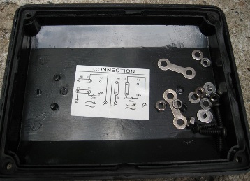
Figure 5
Such a connection is only good if the direction of rotation will never change: once the required direction of rotation is selected with jumpers, and left. As a good example, you can recall at least a circular saw: it spins all the time in one direction, thanks for that.
And who will rearrange these jumpers when controlling the valve? Therefore, it was necessary to develop a reverse circuit based on the unified reversible magnetic starter PML 2621-BMM, which was already available and used with the previous valve.
In one common box two magnetic starters, a thermal relay and three control buttons are combined. In addition to all this, there is a mechanical lock from the operation of two starters at once. In general, a fairly comfortable design.

Figure 6
In this figure, the disassembled starter that will be redone to control the capacitor motor is shown in disassembled form. Neighboring starters are designed to control other valves.
Reverse capacitor motor. Power part
The circuit diagram of the reversing starter was developed by the head of the instrumentation and automation group, Comrade Sukhov S.Yu. Figure 7 shows the power part of the circuit.

Figure 7
Power is supplied to the circuit by selling L and N, which means phase and neutral wires, respectively. The phase is supplied to the engine only when one of the starters is triggered, and the neutral wire is fed directly to the capacitor C1, which is fully consistent with electrical safety measures. Four wires were required to connect the motor.
Mains voltage is supplied, naturally, through a circuit breaker. Moreover, unified magnetic starter contains thermal relay. To simplify the drawing, these elements are not shown in the diagram.
The terminal block on the motor is shown in the rectangle at the top of the circuit. All terminal designations and their location are fully consistent with what can be seen inside the terminal box. Even terminal V2, which is not used, is shown. Magnetic starters are indicated on the diagram as “CLOSE” and “OPEN”, which allows further use of the circuit without any special memory voltage.
The operation of the circuit is easiest to consider if it is assumed that the motor is powered by direct current. Of course, the DC capacitor motor will not work, but if we assume that this is an instantaneous value of alternating current, the proposed description can be considered quite correct. To be even more precise, the diagram shows the point in time when the positive half-period of the mains voltage acts on the wire L.
Figure 8 shows the operation of the engine in the "OPEN" mode.

Figure 8
Valve opening
Conductors L and N are replaced by + and -, therefore, following the direction of the current flow, which is shown in the diagram by arrows, is not difficult: the current goes from “plus” to “minus”. The OPEN starter contacts are circled in red dotted oval, which indicates that the starter is on and the contacts are closed.
The supply voltage from the plus terminal through a closed contact A of the starter K1 is supplied to terminal W2, passes through the coil L2, terminal W1, capacitor C1, and returns to the minus of the power source through terminal V1. Everything, the circuit is closed, the current goes.
You should pay attention to the direction of the current through the coil L2 and capacitor C1: when the “CLOSE” starter is turned on, this direction should not change.
Through terminal B of the "OPEN" starter, a positive voltage is supplied to terminal U1, passes through coil L1 and through terminal U2 and closed contact C of the starter returns to the negative terminal of the power source. In this case, attention should be paid to the direction of the currents in the coils L1 and L2. We can say that the arrows look after each other, as if one is catching up with the other.
Closing valve
The operation of the circuit in the "CLOSE" mode occurs when the K2 starter is turned on.This position is shown in Figure 9.

Figure 9
As in Figure 8, the contacts of the switched on starter are circled in red dotted line. Therefore, we assume that all contacts are closed.
Through the closed contact A of the “CLOSE” starter, the supply voltage is supplied to terminal W2, passes through coil L2, capacitor C1 and through terminal V1 returns to the negative pole of the power source. To be more precise, current flows from voltage. The direction of the current and shown in the diagram by arrows. It should be noted that the direction of the current in the coil L2 is exactly the same as it was in Figure 8.
Now let's see what happens to the L1 coil. The supply voltage, of course, means “plus”, through the closed contact C of the “CLOSE” starter enters terminal U2, current passes through the coil L1, and through terminal U1 and closed contact B of the “CLOSE” starter returns to the “minus” of the source nutrition. In this case, the direction of the current in the coil L1 is opposite to what was shown in Figure 8. From this we can conclude that for reversing the capacitor motor it is enough to change the phasing of one of the coils, in this case it will be the coil L1.
All the previous description, as well as the last two circuits, was made under the assumption that a positive half-period of the mains voltage acts on the phase conductor L. Sooner or later on the line L will be a negative half-cycle. Everything will work in exactly the same way, only in the pictures you have to swap the plus and minus, and the direction of all the arrows is reversed.
How to achieve the “right” direction of rotation
The direction of rotation of the engine should correspond to the pressed control buttons: if the “CLOSE” button is pressed, the valve should go to close. In the case of the “wrong” direction of rotation, the valve opens the other way round.
To correct this misunderstanding, it is necessary to change the direction of rotation, which can be achieved by switching the wires on terminals U1 and U2. For comparison: when using a three-phase motor, the direction of rotation can be changed by switching any two wires, here it is specified above.
Control circuit
With the power unit, everything seems to be clear. It remains only to figure out how this will all be managed. As a matter of fact, the gate valve control algorithm is quite simple: they clicked the “CLOSE” button and closing started, which continues until the “CLOSED” limit switch trips or the “STOP” button is pressed. The same thing happens when the valve is opened, - reached the limit switch, and stopped.
The following is a description of the starter control circuit. In fact, it is an ordinary reversible magnetic starter, which young electricians are invited to assemble at professional skills contests: correctly assembled - get a prize!
But there are several specific elements on this circuit, in particular, limit switches, which are referred to simply as limit switches in professional slang.
Following this tradition, just such a term will be used below. The circuit itself is shown in Figure 10. Basically, it, the circuit, remains the same as when using a three-phase motor.

Figure 10. Valve control circuit
The coils of the magnetic starters K1 and K2 are designed for a voltage of 220V, so the circuit is powered from the phase and neutral wires, labeled L and N, respectively. It is easy to see that the phase wire is connected to the circuit through the STOP button. Such a connection is good already in that when setting the travel limit switches, holding the button de-energizes the entire circuit.
When the “OPEN” button is pressed, the starter K1 is turned on and the contacts K1.1 are set to self-supply. The normally closed contact K1.2 opens, which blocks the inclusion of the K2 starter when the “CLOSE” button is pressed.
The valve starts to open.Opening continues until the end switch SQ1 (OPEN) is activated, located in the valve mechanism or the STOP button is not pressed. The limit switches located in the valve mechanism are shown in a dashed rectangle in the diagram.
The operation of the circuit when the “CLOSE” button is pressed is similar: the K2 starter is turned on and the valve continues to move until the SQ2 (CLOSED) switch trips or the “STOP” button is pressed. Contact K2.2 blocks the inclusion of starter K1. Therefore, changing the direction of rotation of the valve motor is possible only after the mechanism stops.
Release end
Directly in the valve except for the limit switch OPEN. and CLOSE. there are also protective limit switches SQ3, SQ4, also called release. They work when the force of the mechanism exceeds the permissible: a spring is compressed inside the mechanism, which leads to the operation of SQ3 or SQ4. Hence the name of the trailer “release”.
A similar situation most often occurs in the event of a malfunction of the limit switches SQ1 or SQ2: a malfunction of the microswitch mechanism, or even simply welded contacts. This happens quite often.
The operation of the clutch release switches resembles a thermal relay: after operation, you must click on the button to resume the operation of the entire circuit. Only in this case it is required to remove the valve from this position manually, for which each valve has a special handle.
A thermal relay is also present on the circuit. Its normally closed contact is indicated on the diagram as RT - thermal relay.
Connection to the automation system controller
It is easy to connect a similar control circuit to the controller of the water supply automation system using intermediate relays type RP-21 or the like. It is enough to connect the normally open contacts of the corresponding relays in parallel with the “OPEN”, “CLOSE” buttons. To stop the valve in series with the STOP button, you should turn on the normally closed contact of the intermediate relay CLOSE.
In order for the controller to “know” about the position of the valve, optocoupler junctions should be connected to the SQ1, SQ2 ends.
Boris Aladyshkin
See also at i.electricianexp.com
: