Categories: Featured Articles » Practical Electronics
Number of views: 32177
Comments on the article: 0
Entering information into the controller using optocouplers
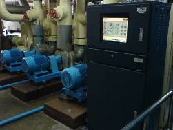 The article describes how, using optocoupler interchanges, to input discrete information with a level of 220 V into the controller, a practical scheme is available for production in any electric laboratory.
In technological processes, it is often necessary to control the position of moving parts of machinery mechanisms. For these purposes, limit switches of various designs and operating principles have been developed and successfully applied.
The simplest in design and principle of operation, of course, are conventional mechanical contact-type switches: through a system of mechanical levers, and often an entire system of gears that drive the cams, an electrical contact is closed, which can mean the final or initial position of the mechanism.
In addition to contact limit switches, or as they are briefly called limit switches, contactless limit switches are widespread. A typical representative of this family are limit switches of the BVK type. There are a lot of modifications, therefore, numbers are put after the letters BVK.
Their work is based on the principle of a controlled relaxation generator. When a metal plate enters the gap gap of such an end switch, generation stops and the output relay trips. Naturally, the aforementioned plate is located on that part of the mechanism, the position of which must be controlled. The appearance of such a trailer is shown in Figure 1.
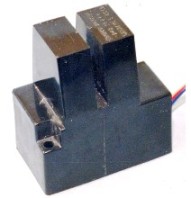
Figure 1. BVK proximity switch
In addition to sensors based on a relaxation generator, induction, capacitive, optical, ultrasonic and other types of sensors are used. But, despite such a variety of types of sensors, and their operating principles, ordinary contact limit switches do not lose their positions, and it is too early to dismiss them.
Often, mechanisms with contact switches are included in automated systems running under control of controllers. In this case, information about the position of the mechanism should be transmitted to the controller that controls the operation of this mechanism.
One of these mechanisms is the most common water valve. Using her example, we will consider how to transfer information about her position to the controller. This is most simply and reliably done using optocoupler isolation. This will be discussed in this article.
Quite often, we are shown on TV how a worker turns a large flywheel at a large valve, shutting off the flow of gas or oil. Therefore, many do not even suspect that the valves are not just mechanized, equipped with electric motors, but also included in various automatic control systems.
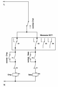
Figure 2 shows a simplified valve control circuit.
Figure 2. A simplified valve control circuit
In order to reduce the volume of the figure, the actual power contacts controlling the electric motor and the electric motor itself, as well as various protection elements, such as circuit breakers and thermal relays, are not shown. After all, the device of a conventional reversible magnetic starter is well known to every electrician. And how many times had to fix the malfunction by simply pressing a button on the "teplushka" !!! But still, the purpose of some elements of the circuit will have to be explained.
The diagram shows the coils of the magnetic starters K1, K2. When K1 is turned on, the valve opens, and when K2 is turned on, it closes, as indicated by the inscriptions near the coils. The starter coils shown in the diagram are rated for 220V.
Normally - closed contacts K2 and K1 is the standard solution for any reversing starter - blocking: when one starter is on, the other one will not be able to turn on.
Opening or closing the valve begins by pressing the corresponding buttons shown in the diagram. After releasing the buttons, the starter is held in the on state by its own contact (block - contact). This mode of operation is called self-feeding. In the diagram, these are normally open contacts K1 and K2.
A little higher than these contacts in the diagram is a rectangle with the contacts inside and the inscription “SME mechanism”. This is a position signaling mechanism (ICP). In our scheme, the valve is in the middle position, so the contacts S1 and S2 are closed, which allows you to turn on any starter, both for opening and closing.
The mechanism of the SME is a gearbox that converts the multi-turn stroke of the working body, in this case the screw pair of the valve, into the angular movement of the shaft with the cams. Depending on the model of SMEs, this angle can be 90 ... 225 degrees. The gear ratio of the gearbox can be any at the request of customers, which allows you to most accurately adjust the position of the cams.
Cams located on the shaft can be rotated to the desired angle and fixed. Due to this, it is possible to obtain various moments of operation of microswitches. In our scheme, this is S1 ... S4. Some modifications of SMEs, in addition to microswitches, contain an induction sensor that outputs analog signal about the angle of rotation of the shaft. As a rule, this is a current signal in the range of 4 ... 20 mA. But we will not consider this signal here.
Now let's get back to our scheme. Suppose the open button has been pressed. In this case, the valve will begin to open, and will open until the microswitch S1 operates in the ICP mechanism. (Unless, of course, the stop button is pressed first). He will de-energize the starter coil K1 and the valve will stop opening.
If the mechanism is in this position, then pressing the open button, the K1 starter will not be able to turn on. The only thing that can cause the electric motor to turn on in this situation is pressing the button to close the valve. Closing will continue until microswitch S2 is activated. (Or until you click "Stop").
Both the opening and closing of the valve can be stopped at any time by pressing the stop button.
As mentioned above, the valve doesn’t work on its own, “they pressed a button and left,” but can enter the automation system. In this case, it is necessary to somehow inform the control unit (controller) of the valve position: open, closed, in the intermediate position.
The easiest way to do this is to use additional contacts, which, incidentally, are already available in SMEs. In the diagram, these are contacts S3 and S4 left free. Only in this case there are additional inconveniences and expenses. First of all, this is that additional wires need to be carried out and additional wires. And this is an additional cost.
Additional inconveniences come down to the fact that you have to configure additional cams. These cams are called informational. In our scheme, these are S3 and S4. Regarding power (in the diagram it is S1 and S2) they must be configured very precisely: for example, the information trailer tells the controller that the valve has already closed and the controller simply turns off the valve. And she still hasn’t reached half!
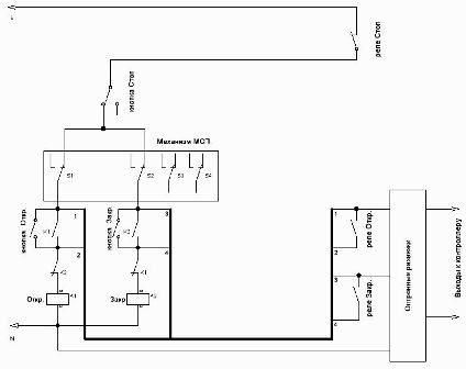
Therefore, Figure 3 shows how to obtain information about the position of the valve using power contacts. For this purpose, optocoupler junctions can be used.
Figure 3
Compared to Figure 2, new elements have appeared in the diagram. First of all it relay contacts with the names “Relay Open”, “Relay Close”, “Relay Stop”.It is easy to notice that the first two are connected in parallel to the corresponding buttons on the hand control panel, and the normally closed contacts are “relay Stop.” sequentially with the Stop button. Therefore, at any time, the valve can be controlled either by pressing the buttons by hand, or from the control unit (controller) using intermediate relays. To simplify the circuit, coils of intermediate relays are not shown.
In addition, a rectangle appeared on the diagram with the inscription "Optocoupler interchanges." It contains two channels that allow the voltage from the limit switches of the SME mechanism, and this is 220V, to be converted into the signal level of the controller, as well as to carry out galvanic isolation from the power network.
The diagram shows that the inputs of the optocoupler junctions are connected directly to the microswitches S1 and S2 of the ICP mechanism. If the valve is in the middle position (partially open), both microswitches are closed and a voltage of 220 V is present at both inputs of the optocoupler junctions. In this case, the output transistors of both channels will be in the open state.
When the valve is fully open, the microswitch S1 is open, there is no voltage at the input of the optocoupler isolation channel, so the output transistor of one channel will be closed. The same can be said about the operation of microswitch S2.
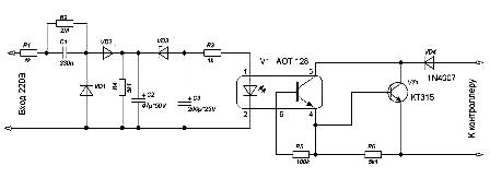
A schematic diagram of one optocoupler isolation channel is shown in Figure 4.
Figure 4. Schematic diagram of one optocoupler channel
Description of the circuit diagram
The input voltage through the resistor R1 and capacitor C1 is rectified by the diodes VD1, VD2 and charges the capacitor C2. When the voltage across the capacitor C2 reaches the breakdown voltage of the zener diode VD3, the capacitor C3 is charged and through the resistor R3 “lights” the optocoupler LED V1, which leads to the opening of the optocoupler transistor, and with it the output transistor VT1. The output transistor is connected to the controller input through a decoupling diode VD4.
A few words about the purpose and types of parts.
Capacitor C1 works as a non-watt resistor. Its capacitance limits the input current. The resistor R1 is designed to limit the inrush current at the moment of closing of the microswitches S1, S2.
The resistor R2 protects the capacitor C2 from increased voltage in the event of an open in the Zener diode VD3 circuit.
As a Zener diode VD3, KC515 with a stabilization voltage of 15V is used. At this level, the charge voltage of the capacitor C4 is limited and, accordingly, the current through the LED of the optocoupler V1.
AOT128 was used as the optocoupler V1. 100 kOhm resistor R5 keeps closed optocoupler phototransistor in the absence of LED illumination.
If instead of the domestic AOT128 optocoupler, we use its imported analog 4N35 (although this is still a question, which of them is the analog?), Then the resistor R5 should be put with a nominal value of 1MΩ. Otherwise, the bourgeois optocoupler simply will not work: 100 KOhm will close the phototransistor so firmly that it will no longer be possible to open it.
The output stage on the KT315 transistor is designed to operate with a current of 20 mA. If you need a larger output current, you can use a more powerful transistor, such as KT972 or KT815.
The scheme is quite simple, reliable in operation and not capricious in commissioning. You can even say that it does not need adjustment.
The easiest way to check the operation of the board is by applying a 220V network voltage directly from the outlet. Connect an LED through an resistor of about one kilo-ohm to the output and apply a 12V voltage. In this case, the LED should light up. If you turn off the 220V voltage, then the LED must go out.
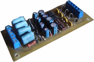
Fig. 5. Appearance of the finished board with optoelectronic isolation
Figure 5 shows the appearance of a finished board containing four opto-coupler channels. The input and output signals are connected using the terminal blocks installed on the board. Pay made by laser - ironing technology, because it was done for its production.For several years of operation, there were practically no failures.
Boris Aladyshkin
See also at bgv.electricianexp.com
:

