Categories: Featured Articles » Electrician Secrets
Number of views: 70778
Comments on the article: 1
AutoCAD Electrical CAD System
 Once, thanks to AutoCAD, designers switched from working on computers to computers. However, modern projects are so complex, and their production deadlines are so tight that AutoCAD no longer meets all modern design requirements.
Currently, various computer-aided design systems are actively crowding out the "electronic culman", offering to accelerate the implementation of the project, automate routine work, control the design process and warn about errors.
AutoCAD Electrical - this is a well-known AutoCAD for creating projects in the field of electrical engineering, automation, process control systems, Instrumentation and other areas.
The program contains a full set of AutoCAD functions, to which specialized tools are added that automate the processes of creating diagrams, layout drawings, report generation, etc. Designing in AutoCAD Electrical can improve productivity and reduce errors.
If AutoCAD works with separate drawings, geometric objects and blocks, then AutoCAD Electrical works:
-
With the whole project, including the project, you can create from standard drawings and typical fragments of schemes
-
With components, such as motors, relays, terminals, connectors, etc.
-
Wires, cables and harnesses
-
Programmable Logic Controllers, etc.
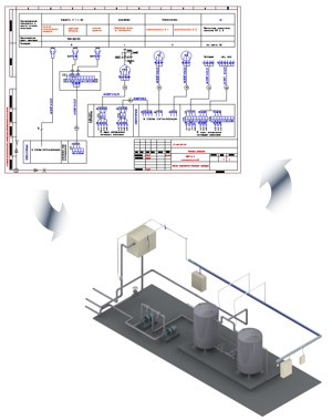
Autodesk’s digital prototype technology solution goes beyond the usual 3D modeling. It allows working groups to use the same digital model at all stages of the project - from the conceptual design to the design, design of electrical control elements and production.
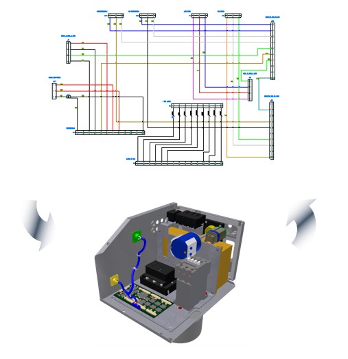
Click on image to enlarge
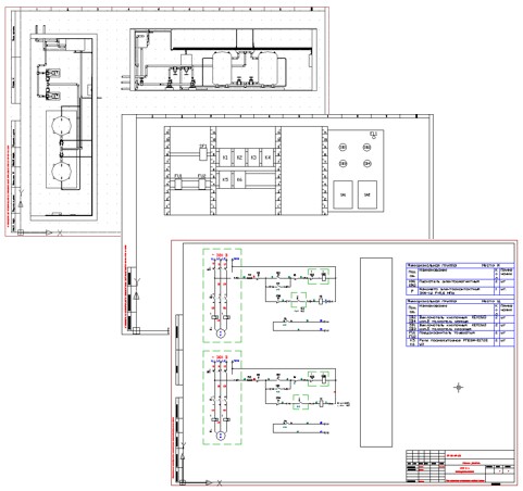
An AutoCAD Electrical project may contain:
-
Automation schemes
-
Electrical schematic diagrams
-
Wiring diagrams
-
Layout Drawings
-
Assembly plans
-
Various reports and other documents
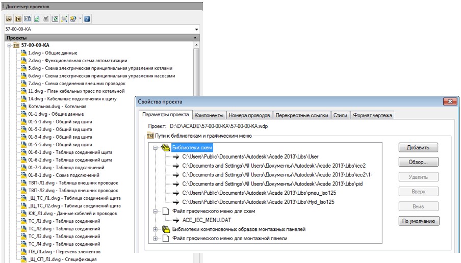
Work with projects and drawings in AutoCAD Electrical is coordinated by the "Project Manager", which offers:
-
Flexible means of adjusting the display of project content
-
Powerful shortcut menu
-
Tools for setting up the project environment and component libraries.
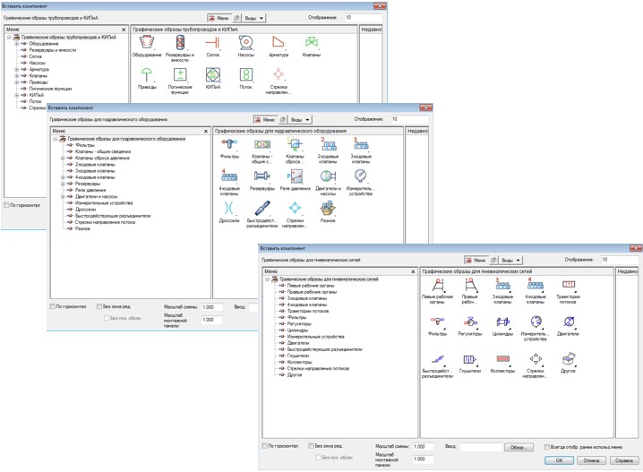
When working on a project, graphic and text databases are used. The AutoCAD Electrical supply includes more than 2000 conventional graphic symbols (UGO) of electrical circuit components according to GOST, JIC, IEC, GB, JIS, AUS. It is possible to create custom graphic images and include them in a graphic database.
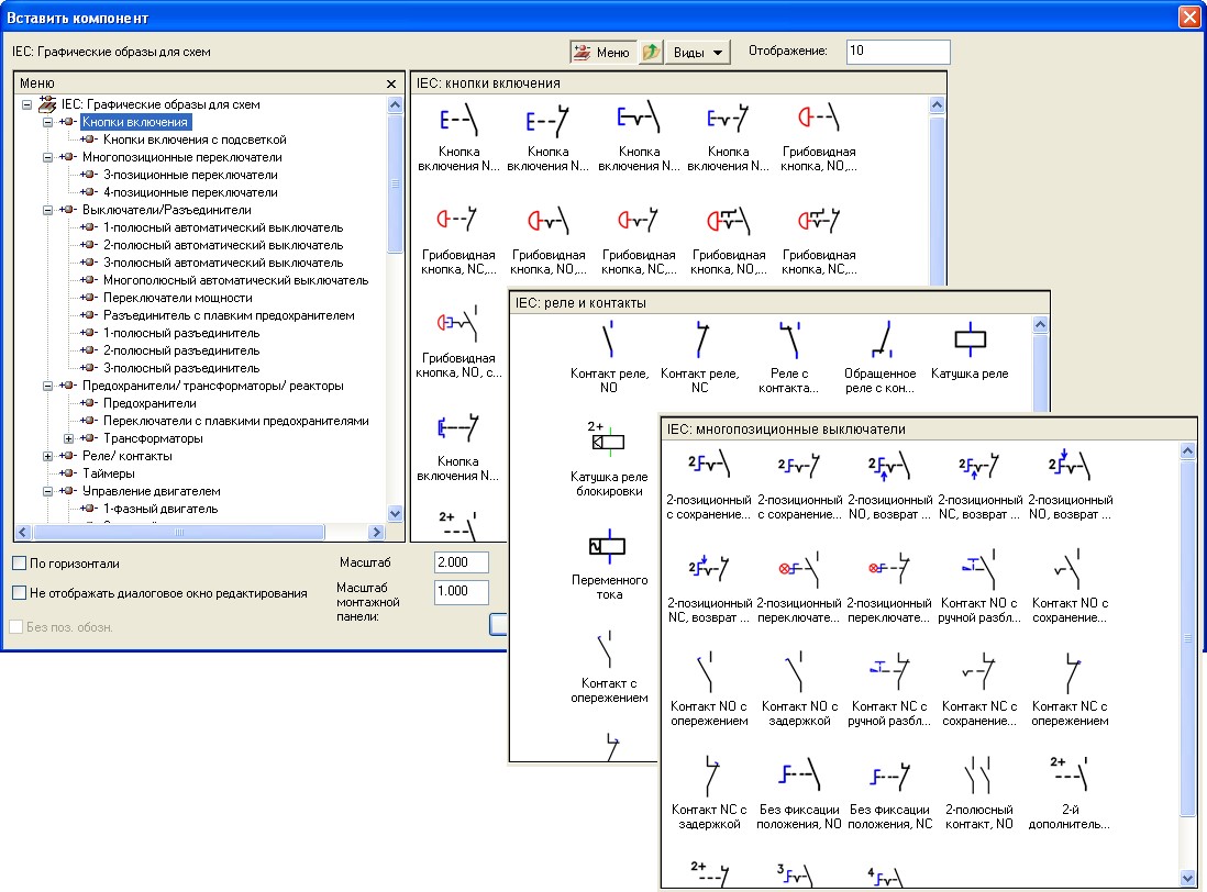
The graphical component library also includes:
-
Product layouts
-
Automation Circuit Components
-
Pneumatic and hydraulic components.
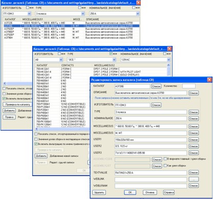
AutoCAD Electrical catalog database contains more than 350 thousand items of products from the most famous manufacturers, their catalog data and layout images.
A component placed on a layout diagram or drawing is automatically assigned a unique reference designator. Lines created in special layers are defined as wires or circuits, which are also automatically assigned a unique number.
AutoCAD Electrical supports:
-
Flexible format for component designations and project circuit numbers
-
3-Phase Numbering
-
Track duplicate notation.
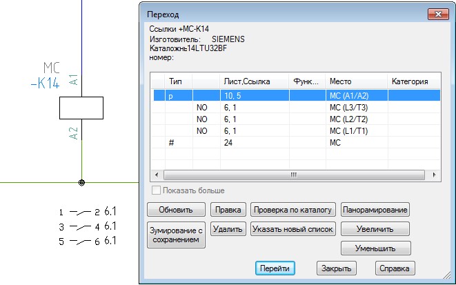
Graphic images of component parts located on different sheets of the project, but with the same reference designator, are defined by AutoCAD Electrical as a single object. A special tool allows you to automatically find the component parts and move around them, making, for example, the necessary changes. Changes made in one part of the component are transferred to all other parts.
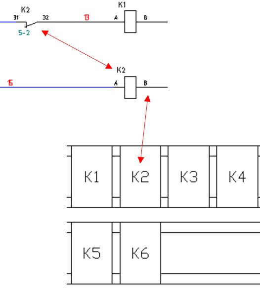
Special functions for working with contactors / relays are supported, including:
-
Flexible display format for cross-references: text, graphic or tabular, the ability to display unused contact groups
-
Warning about exceeding the number of contact groups and inadmissible contacts.
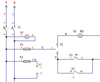
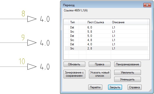
To connect chains on different sheets of the project or in different parts of the sheet, cross-links of chains are used: source links and destination links.
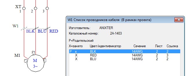
In addition to the number of wires of the project, you can assign a brand, color, section and other characteristics. With special tools, wires are assigned the functions of cable cores, which are assigned the cable cable designation and catalog data, core numbers, etc. AutoCAD Electrical controls the permissible number of cores for the selected cable type.
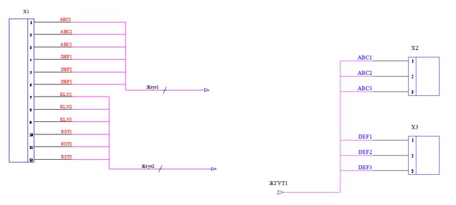
AutoCAD Electrical offers the following tools for creating circuits using wire harnesses:
-
A parametric way to create connectors
-
Building multiple conductors in one operation
-
Numerous connector pin functions
-
Links - Splitters for Harnesses
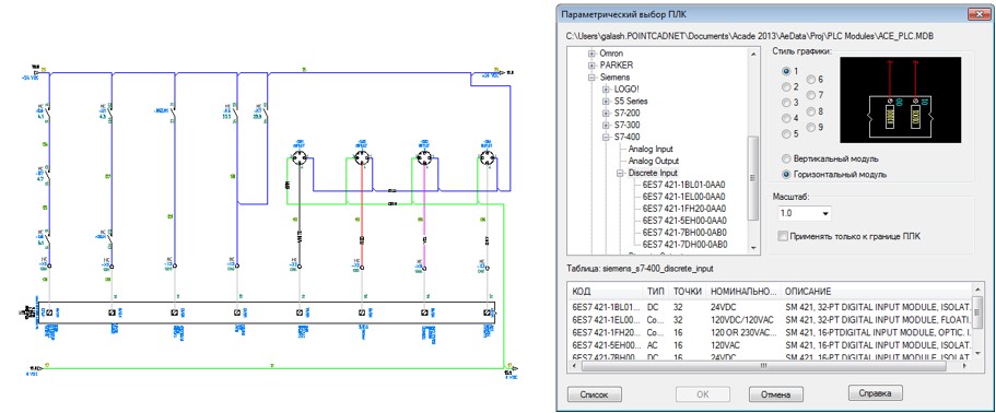
The following features are available for automated circuit creation using programmable logic controllers (PLCs):
-
The PLC module library contains more than 3 thousand products of the most famous manufacturers
-
Parametric placement and designation of PLC I / O modules on project sheets
-
Automatic creation of PLC I / O module connection drawings based on tabular data
-
Bidirectional communication between AutoCAD Electrical and Rockwell Automation, as well as Schneider Electric’s Unity.
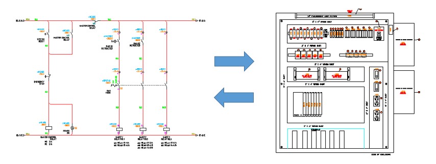
The following AutoCAD Electrical features allow you to create smart layout drawings:
-
Communication and control of component display on the diagram, layout drawing and in reports
-
Interactive creation of layout drawings according to project diagrams
-
Adding structural elements, ducts and mounting rails to the project
-
Adding and controlling item numbers for components
-
Project Integrity Check
-
Cross-reference navigation between component display parts
-
Possibility to apply assembly data to the drawing.
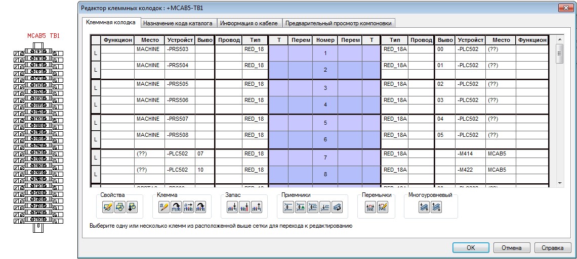
All information about the project terminals is transferred to the "Terminal Block Editor", which provides the following features:
-
Adding redundant terminals, internal and external jumpers, accessories
-
Generation of display of terminal blocks in graphical or tabular form
-
Create multi-level terminals
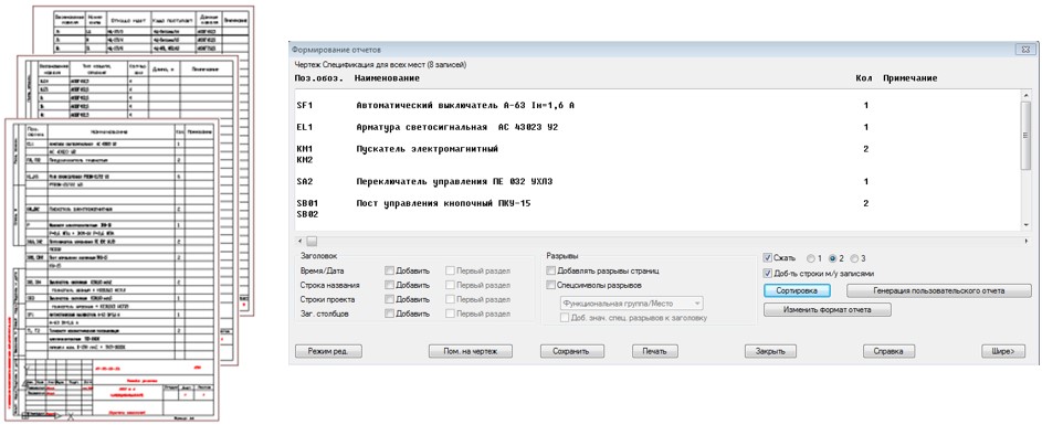
According to the project or individual drawings, various reports are automatically generated, such as a list of elements, connection tables, external wiring, PLC signals and other documents. To obtain the required report formats, there are:
-
Ability to customize user reports, report generation in accordance with GOST
-
Sort and filter fields
-
Configuring the display of a report on a sheet of a schematic or layout drawing
-
Bidirectional transition from sheet to report display is supported.
-
ASCII, Microsoft Excel, Microsoft Access, CSV and XML are supported for saving reports in external files.
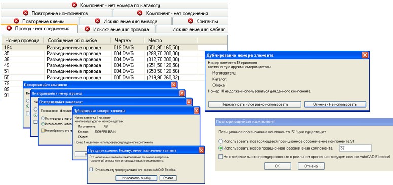
In the design process, real-time monitoring is carried out and error messages are displayed. Objects and tools of control:
-
UGO for components
-
Duplication of component, terminal, cable or core number designation
-
Missing or redialing wire number
-
Hanging wires
-
Non-assigned part numbers
-
“Child” components for which a “parent” component is not assigned
-
Invalid contacts
-
Assigning the component position number in the cabinet, etc.
To obtain a three-dimensional model of the product, there is a connection with Autodesk Inventor Professional. The following procedure for sharing AutoCAD Electrical and Autodesk Inventor Professional is suggested:
-
Create circuits in AutoCAD Electrical and save project data in XML format
-
Read circuit diagrams and auto-wire routing in Autodesk Inventor Professional to get cable lengths and diameters
-
Harness Drawing Generation
-
Correction of schemes according to data from a 3D model
See also at i.electricianexp.com
: