Categories: Novice electricians, Industrial electrician
Number of views: 86353
Comments on the article: 4
What are wiring diagrams and where do they apply
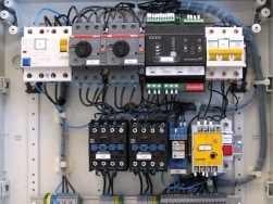 Modern electrical equipment in its work uses numerous technological processes that proceed according to various algorithms. An employee engaged in its operation, maintenance, installation, commissioning and repair must have reliable information about all their features.
Providing the events in graphical form with the designation of each element in a specific, standard way, greatly facilitates this process, allows you to transfer the intentions of the developers to other specialists in an understandable form.
Appointment
Electrical circuits are created for electricians of all specialties, have various design features. Among the methods for their classification, dividing by:
-
principal;
-
assembly.
Both types of circuits are interconnected. They complement each other’s information, are carried out according to common standards, understandable to all users, have differences in purpose:
-
Schematic diagrams are created to show the principles of operation and interaction of constituent elements in the order of their operation. They demonstrate the logic embedded in the technology of the applied system;
-
wiring diagrams are made as drawings or sketches of parts of electrical equipment, which are used for assembly, installation of electrical installations. They take into account the location, layout of the components and display all the electrical connections between them.
Wiring diagrams are created on the basis of the principal and contain all the necessary information on the installation of electrical installations, including the implementation of electrical connections. Without their use, it is impossible to create high-quality, reliable and understandable electrical connections for modern equipment for all specialists.
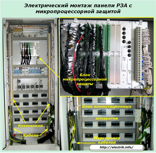
The protection panel shown in the photo is connected by numerous cables to measuring current and voltage transformers, power executive equipment, logical deviceshundreds of meters apart. Correctly assemble it only by a well-prepared wiring diagram.
How are wiring diagrams created?
First, the developer creates a circuit diagram, which shows all the elements used by him and how to connect them with wires.
An example of a simple connection of a DC motor to a power circuit using a contactor K, and two buttons KN1 and KN2, demonstrates this method.
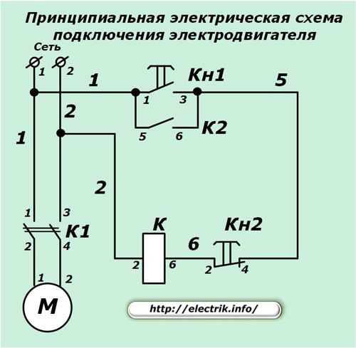
Powerful normally open contacts of the contactor 1-2 and 3-4 allow you to control the operation of the electric motor M, and 5-6 is used to create a self-holding circuit of the A-B winding under voltage after pressing and releasing the KN1 "Start" button with make contact 1-3.
Button Kn2 “Stop” with its opening contact removes power from the winding of contactor K.
The positive voltage potential “+” is applied to the electric motor through a wire marked with the number “1” and “-” - “2”. The remaining wires are indicated by the numbers "5" and "6". The method of marking them may be different, for example, with the addition of letters and symbols.
In this way, on the circuit diagram, all the contacts of the windings, switching devices and connecting wires are shown. Other information required for operation may also be indicated.
After the circuit diagram is created for it, an assembly circuit is developed. It depicts those elements that are involved in the work. Moreover, all existing contacts of switching devices, buttons (example of Кн1 and Кн2), contactors and relays, and only used in the case under consideration (example of contactor K) can be displayed to simplify the perception.
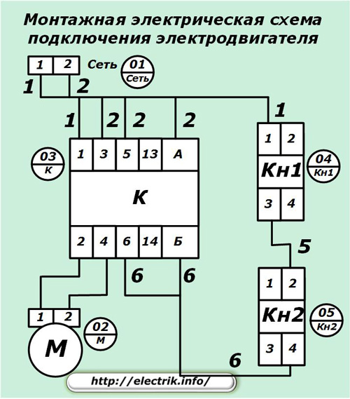
All mounting units are numbered with an individual number for each item. For example, in our diagram are indicated:
-
01 - terminal block for connecting power circuits;
-
02 - motor contacts;
-
03 - contactor;
-
04 - button "Start";
-
05 - “Stop” button.
The contacts of buttons, relays, starters and all electrical elements of the circuit are numbered on the housing of each device or indicated by a specific position in the technical documentation.
Images of wires are carried out by straight lines and marked in the same way as in the circuit diagram. In the considered option, they are assigned numbers 1, 2, 5, 6.
How to read and assemble wiring diagrams
During the assembly of complex circuits, it is convenient to work immediately with the installation and circuit diagrams. They supplement general information that can be difficult to keep in mind.
At the same time, it should be understood that the ideas depicted on paper should be implemented on real equipment and read as well as well, be informative. For this purpose, any element is signed, indicated, marked.
Designations of devices and apparatus
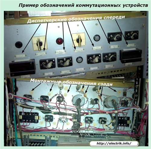
On the front side of the panels, control cabinets, inscriptions are made explaining to the operating personnel the purpose of each electrical device, and for switching devices - the position of the switching organ corresponding to each mode.
Keys and buttons are signed by the action taken, for example, “Start”, “Stop”, “Test”. The signal lights indicate the nature of the signal, for example, "Blinker is not raised."
On the reverse side of the panel, a sticker (usually round) is placed against each element, indicating the fraction of the mounting position according to the diagram above and a brief designation of the installation diagram below, for example, 019 / HL3 for an alarm lamp.
Wire designations
When installing equipment at each end of the wire put on cambric signed resistant to fading in the light and indelible ink, indicating the accepted marking. They are connected to the indicated terminals. When the designation contains only the numbers "0", "9". “6”, then after them they put a point excluding the incorrect reading of the information when considering the inscription on the reverse side.
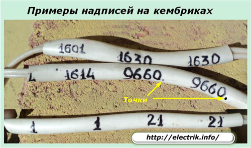
For simple equipment, this technique is enough.
On complex and branched systems add the return address of the end. It consists of two parts:
1. first comes the numbering of the position designation of the element connected on the reverse side;
2. Next is the terminal number.
For example, at terminal 2 of the Kn2 button, a wire should be connected with the cambric worn, signed 5-04-3. This inscription stands for:
-
5 - wire marking according to the mounting and circuit diagram;
-
04 - mounting unit number of the Start button;
-
3 - terminal number Кн1.
The sequence of alternation, as well as the use of brackets or other separators of signs, can change, but it is important to do it uniformly in all parts of the electrical installation. Marking must be carried out in strict accordance with the working drawings and wiring diagram.
It allows specialists to read the mounted circuit from life as conveniently as from a paper sheet, which needs to be done quickly when troubleshooting or preventive maintenance.
For information: earlier marking of the ends of the wires was carried out:
-
donning porcelain tips with the designation of the marks with oil paints;
-
hanging aluminum tokens with stamped information;
-
securing cardboard tags with ink or pencil inscriptions;
-
other available ways.
The wiring diagram may be supplemented or replaced by a wire connection table. She points out:
-
marking of each wire;
-
start of its connection;
-
reverse end;
-
grade, type of metal, cross-sectional area;
-
other information.
Cable designations
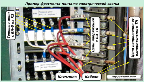
A mandatory element of each electrical installation is a cable magazine, created for each individual connection on complex sections or one common for several simple ones. It contains complete information about each cable connection.
For instance, at an outdoor switchgear of a 110 kV substation with power sectioned buses and switches controlling the operation of 25 overhead power lines, an assembly connection is created for each overhead line. It is assigned an individual number, which is indicated in the documentation and on the equipment.
Line No. 19 from this switchgear is given the operational dispatch name for the main locality of the power supply and the mounting designation, for example, 19-SL, which is affixed to all equipment, including secondary cable networks of this overhead line at the substation.
In addition to the cable belonging to the line, the cable magazine and the equipment indicate its attribute as intended, for example:
-
measuring current or voltage circuits;
-
automation or control circuit;
-
protections;
-
signaling;
-
blocking;
-
other secondary devices.
When installing electrical circuits, cable lines of various lengths can be used. At the entrance to the panel or cabinet, their number can be quite large. All of them are marked at both ends, as well as when crossing through the walls of the building and other building structures.
A tag is hung on the cable with information indicating its affiliation, purpose, brand, composition of cores. When cutting it, each wire is marked. The ends connected to the electric circuit are marked with information about the cable accessory, the number of the switched terminal on the terminal block and the chain designation.
Loose cable cores in reserve, as well as workers, must be called up and marked. But, in practice, this requirement is rarely implemented.
Features of the designation of individual elements in wiring diagrams
According to local conditions, they sometimes deviate from generally accepted rules, facilitate the drawing of circuits and the installation of electrical circuits without prejudice to their reading from life.
Most often this occurs when:
-
hinged installation of parts directly to the contact terminals of relays and devices;
-
setting short, clearly visible jumpers.
Mounted Mounting
An example of installing diodes VD4 and VD5 parallel to the terminals of the windings AB in relays K3 and K4 is shown in a fragment of the wiring diagram.
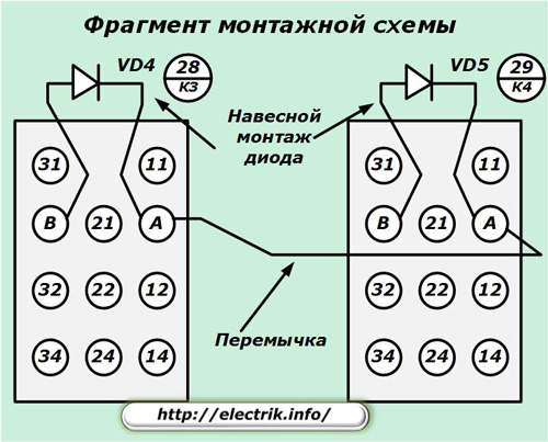
In this situation, they are mounted directly, without marking and signatures.
Jumpers
The same fragment shows the installation of a jumper between the same terminals A of the windings of the same relays.
Installation of electrical equipment is carried out according to the basic and wiring diagrams created according to uniform rules. It must meet the requirements of visibility, accessibility, information content so that repairs and maintenance work are carried out quickly and efficiently.
See also at bgv.electricianexp.com
:

