Categories: Featured Articles » Novice electricians
Number of views: 112927
Comments on the article: 2
What are electrical circuits for and what types are they
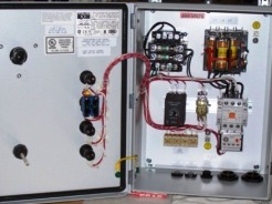 There are several different types of electrical circuits and any competent electrician must be sure to understand why they are needed, how they differ from each other, what information they contain, what conventions are used on different circuits, how to read them correctly.
Very often people confuse the terms “types” and “types” of schemes. By type of circuit, they are divided into electric, pneumatic, hydraulic and combined. Combined circuits are most common in projects of automation of various technological processes, when in projects together with various electric motors, devices, sensors, elements of pneumatic automation and hydraulics are simultaneously used. Such schemes are called combined electro-pneumatic, electro-pneumatic or electro-hydraulic.
By type, all electrical circuits are divided into functional, structural, circuit, connections and connections (mounting) and location. There are special types of circuits, for example, external electrical and pipe wiring diagrams, cable routing schemes. They perform installation and connection of wiring to electrical equipment and automation.
The most common type of electrical circuitry is electrical circuit diagrams. They give a clear understanding of the operation of the installation, since such circuits show all the electrical circuits. On electrical schematic diagrams, the conventional symbols depict all electrical elements, apparatuses and devices, taking into account the real sequence of their work.
If this is a circuit of any machine, then the power part of the circuit (electric motors and all the devices through which they are connected) and the control circuit are separately shown. All elements on the circuit diagrams have alphanumeric designations, which are performed according to GOST.
The circuits are usually supplemented by various diagrams and contact switching tables, which explain the operation of complex elements, for example multi-position switches, timing diagrams showing the sequence of operation of the relay coils.
The specification may appear on the diagram with a list of electrical devices and other electrical devices and elements included in the circuit, additional explanatory inscriptions. After reading the schematic diagram, you can study and fully understand how the electrical equipment of the installation or machine works.
The electrical circuit diagrams can be performed in a combined or spaced manner. In a combined way, relatively simple circuit diagrams are usually performed. Schemes in which several engines and an advanced control scheme are in most cases carried out in an exploded way.
Separate elements of the symbols of electrical devices are located in different places of the circuit, while this increases the visibility and simplifies the reading of circuits.
To read the circuit diagrams, it is necessary to know the algorithm of the circuit operation, to understand the principle of operation of devices, apparatuses and automation systems, on the basis of which the circuit diagram is built.
According to the electrical schematic diagram, the correctness of the electrical connections during installation and commissioning of electrical equipment is checked. Such schemes are indispensable in the operation and troubleshooting during repairs. Although I once met at the factory old electricians working without circuits (often they simply did not exist), but this still does not mean anything. In this case, people simply benefited from the experience of maintaining the same machines for a long time.
If there is no such experience, then troubleshooting even in the electrical equipment of machines of relatively small complexity can cause serious difficulties and stretch for hours. Therefore, the circuit diagram is the main lifesaver of any electrician. Thanks to it, any malfunction can be detected and eliminated in a very short time.
Using electrical circuitry design wiring diagrams and connections. In another way, such schemes are popularly called installation circuits. Such schemes show the actual location of electric motors, electrical devices and other automation elements on the machine, in cabinets and on control panels. All items on wiring diagrams are performed similarly according to the same GOST as in the schematic diagrams.
A simplified wiring diagram and connecting a three-phase motor using two magnetic starters:
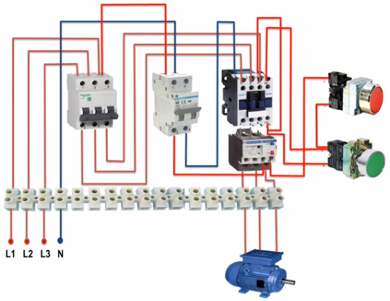
All wires on the connection and connection diagram have their own unique number, which, after mounting the real circuit, is applied to the wire. In such schemes, wires going in one direction are often combined into bundles or bundles and shown with one thick line. All wire connections are made only at the terminals of electrical devices or with special terminal blocks. All connections between parts of individual cabinets and control panels are also made through the terminal strip, which greatly facilitates the maintenance of electrical equipment of machines.
If on the circuit diagrams the individual elements of the same apparatus can be located in different parts of the circuit, for example, the starter coil in the control circuits, and the contacts in the power circuits, then on the wiring diagram and connections all the elements of the same starter are shown side by side. In this case, the conclusions of the device on the circuit are numbered in the same way as on a real device.
For example, for the starter, the coil outputs are numbered - A - B, power contact - 1-2, 3-4, 5-6, blocking 13-14. This greatly facilitates the installation of electrical equipment. A person who does this does not have to think about where to place the device itself (this is already shown in the diagram) and where to connect which wire. Since the presence of the number on the locking contact "13-14" indicates that this contact is normally open. If the contact were normally closed, then the number would be "11-12".
Very often in the machine passports the connection and connection diagrams are shown separately. The wiring diagrams indicate the contours of the machine or installation, the main elements are motors, devices located on the machine itself (trip switches, sensors, electromagnets), cabinets and control panels, as well as electrical wiring that all connect it. Cabinets and control panels show empty circuits with terminal blocks to which the wires lead. And the connection diagrams depict only a specific control cabinet with all the devices included in it and the wiring. At the same time, on the connection diagrams, emphasis is placed on the description of the location and methods of fastening wires, bundles, pipes, electrical apparatuses and electric motors on the machine itself.
There are several options for performing connection and connection schemes. One of the most popular methods recently is the address method. In this method, the wires in the diagrams are not shown, but only indicated by numbers near the terminals of electrical devices. Although such a circuit is easier to execute when using computer programs, in my opinion, it turns out to be much more complicated and often leads to installation errors.
Read more about this type of circuit here: What are wiring diagrams and where do they apply
In addition to electrical principle and installation are common structural and functional diagrams. They help to understand the general principle of operation of any complex equipment or individual elements.Structural schemes differ from functional ones in that the basic functional parts of the device are defined and indicated in the first type of circuits, and the processes that occur in them are explained on the functional circuits, i.e. the principle of operation of the device is explained.
For example, such circuits are very popular in describing the principle of operation of complex electronic devices. In this case, the detailed circuit diagram can only confuse and frighten, especially not experienced electricians, who for the most part are very afraid of various electronics. And so, having figured out the structural diagram of which individual blocks the device consists of, how these blocks interact with each other, understanding how the specific blocks and elements of the device work by the functional diagram and then turning to the problematic part in the circuit diagram, you can quickly solve any problem that has arisen.
There are also joint schemes. Such circuits may show several types of circuits, for example, electrical circuit and wiring, or circuit and layout. The block diagram can be combined with the functional.
See also: Programs for creating electrical circuits
P.S. A few examples of various types of electrical circuits.
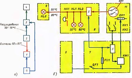
Example of structural (a) and functional diagram (b)
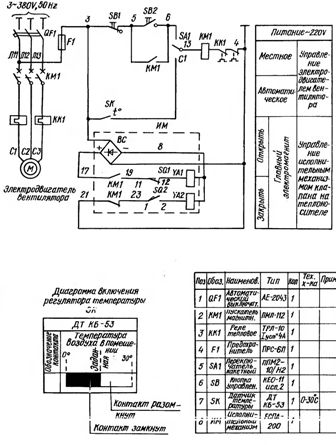
An example of the electrical circuit
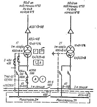
Schematic diagram of a factory transformer substation
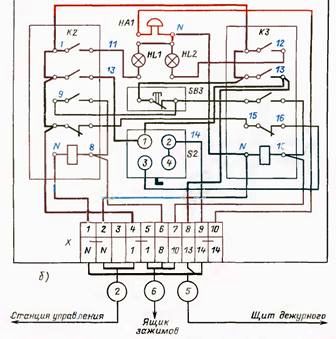
Connection diagram of the shield with electrical equipment
See also at bgv.electricianexp.com
:
