Categories: Featured Articles » Interesting Facts
Number of views: 13549
Comments on the article: 2
Closed loop wiring and its use
History of ring wiring
Surviving the aftermath of World War II, Britain entered into a massive housing restructuring program, as many houses were simply destroyed as a result of the war.
An acute shortage of copper forced material to be saved, and engineers had to come up with a wiring diagram that would allow the use of the available copper in the most optimal cost-effective way. Moreover, it was necessary to obtain wiring for normal operation with 13-amp sockets equipped with fuses.
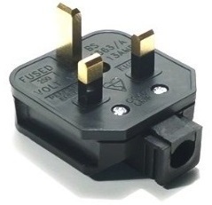
BS1363 sockets and plugs with a fuse with rectangular contacts were then a popular unified solution, and a wiring diagram was developed for them from 1942 to 1947.


So a ring wiring was developed, allowing the connection of a pair of electric heaters with a capacity of 3 kW each, in any of two places in the house, and allowing you to power low-power devices, and the copper consumption was minimal.
Ring wiring has become the most common solution in the UK, besides it could easily be converted to a 20-amp radial just by breaking the rings in half, and feeding the halves through separate machines. In addition, it was possible to resort to a radial scheme if one of the branches of the ring was damaged, and it took time to repair. Replacing the wiring, again, was very simple.
Another advantage of ring wiring is lower installation labor. It was enough to have already existing, radially connected sockets plugged into a 30 ampere ring with a wire, and then add more sockets if necessary. The ring turned out to be unusually connected to the network - through a pair of fuses of 15 amperes, but it worked well.
What is a ring wiring
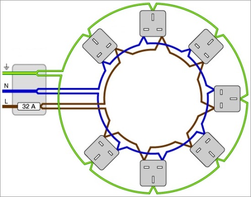
Designed and used in the UK, ring wiring involves the use of independent pair conductors for neutral, phase and grounding at each outlet. This approach allows the use of twice as thin a conductor as compared with conventional radial wiring for current of a similar magnitude.
In the ideal case, the ring works as two parallel radial current-carrying branches of the wire, turned in the opposite direction, and in reality the point of separation of the branches varies depending on which points of the ring the consumers are connected to at the moment.

When the load is distributed evenly along the ring, then the current on each side will have half of the total. Therefore, the cross section of the conductor can be used half as much. But in fact, the load is by no means everywhere and it does not always turn out to be distributed symmetrically, so in reality the wire is taken thicker than the calculated one.
How to install ring wiring
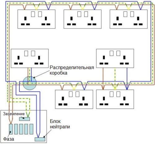
The beginning of the ring is from the switchboard of the apartment. The wire is led alternately to each outlet, after which it returns back to the shield. For a three-phase system, one ring is fed through one single-pole circuit breaker in the switchboard. Typically, for a 13-ampere ring wiring, a cross-section of 2.5 square mm is taken (for the British standard), and the machine is set to 32 amperes.
If the wiring comes out long, or thermal insulation reduces the characteristics of the cable, then to reduce voltage drops and losses, a wire with a cross-section of 4 sq. Mm in PVC insulation is used. Or if the cable is in mineral insulation and in a copper sheath, then they take a core cross-section equal to 1.5 square mm for the same 13 amperes, since such a cable can withstand heating more easily, but then wiring must be calculated with high accuracy, taking into account voltage drops over long plots.

According to European rules for ring wiring, the cable cross-section is taken based on a current of at least 2/3 of the rating of the protective device. In this way, the likelihood of a prolonged overload for the core is minimized. Almost often, the machine is slightly further at par from the proposed ratio.
According to the rules of BS 7671, it is allowed to install any number of standard outlets on a ring circuit if the area of the room is not more than 100 squares, but in practically not very large houses they make one wiring ring per floor. If the house is large - several rings are made, in the end, the designer decides it on the basis of his own experience. Often a separate ring is made for the kitchen or for that place in the home where powerful consumers are installed.
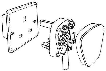
If the branch from the ring is made with a cable of the same thickness as the cable of the ring, then the fuses can not be installed, but immediately connect a single or double outlet. Branches are connected to the ring using junction boxes. If the outlet is triple or even more complex, then it needs a fuse (usually it is already built-in).
There should not be more taps than outlets. It is believed that doing additional bends is bad practice. If the outlet requires several outlets for low-power consumers, then a switchgear equipped with its own fuse or even with a switch (for several stationary units) is immediately used.
When a device with a capacity of more than 3 kW is supposed to be installed in a building, such as a powerful boiler or heater, that is, a device that will work for a long time and consume more power, it is not recommended to connect such a device directly to the ring. Better to lay him a separate branch.
Disadvantages of ring wiring
Some disadvantages of ring wiring make it not very popular outside the UK. The main disadvantage is the non-obviousness of the emergency mode.
If the ring (phase, neutral or ground) is broken for some reason, and the load continues to be fed, the person does not notice a malfunction, and the cable is overloaded - the current may already be higher than the rating and the cable quickly breaks down. In the worst case, there is a danger of fire.
Conventional radial wiring would simply cease to conduct current or work RCD. Too many bends, or if they are too long, also exacerbate the possibility of overheating, for reliability, adequate protection on each branch is necessary.
Testing ring wiring requires 5 times more work than testing traditional radial circuits, and not every electrician can test a ring circuit.
The BS 7671 standard prescribes the rule that none of the ring sections should experience current overload (current should not flow over a single piece of cable), and this is a difficult requirement, and it is often ignored. For example, a washing machine and a dishwasher are not installed close to the center of the ring, and that’s all, the requirement has already been violated.
Ring wiring is a source of unwanted magnetic field. In the traditional scheme, the current flows through two wires lying side by side, and the magnetic fields from the two wires neutralize each other, a large current loop is not formed, an inductor is not formed - a magnetic field source.
But the ring circuit, in the case of inequality of currents on both sides of the ring in the phase and neutral wires, will create an alternating magnetic field inside the ring, and this electromagnetic interference, which will interfere with other devices, in particular sound, will lead to abnormal alarms, inducing EMF to grounded conductors interfere with the operation of medical vital devices, etc.
Finally, how to provide ring wiring with adequate protection against overloads, especially with implicit damage? Additional fuses are needed, and better - in each outlet or plug.
Of course, individual fuses are an excellent solution, since a failed device will immediately identify itself, and other devices will continue to work.
But in the end, there are a lot of stumbling blocks, especially for those countries where it is not customary to use plugs with individual fuses in the UK. So is the game worth the candle?
See also at i.electricianexp.com
:
