Categories: Novice electricians, Industrial electrician
Number of views: 20854
Comments on the article: 0
Operation and repair of electromagnetic relays
The relay has a limited resource, this is primarily due to the principle of its operation: the electromechanical relay operates due to the magnetic field and the closure of mechanical contacts. Mechanical contacts wear out, the coil burns out, hence the need for repair. Most often, the repair consists in cleaning the contacts or solving problems with the coil.
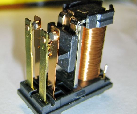
Design and typical problems
Before moving on to repair issues, let's go through the components electromagnetic relay. The relay itself compares the magnitude of the control action, after which the signal is transmitted to the controlled circuit.
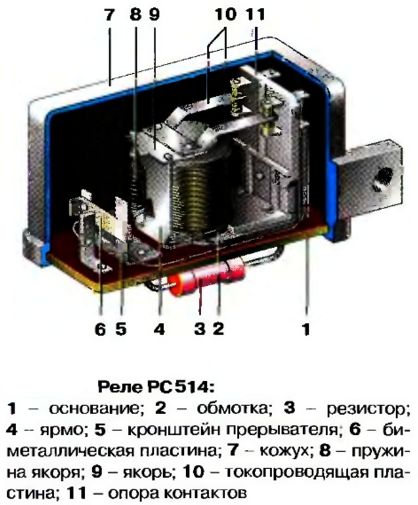
In our case, an electric current is supplied to the coil. The anchor is attracted to the core of the coil due to the magnetic force created by the magnetic flux.
The relay is triggered if sufficient voltage and current are supplied. When the electromagnet trips, the contacts close. There can be several groups of contacts, as well as pairs of normally closed and normally open contacts.
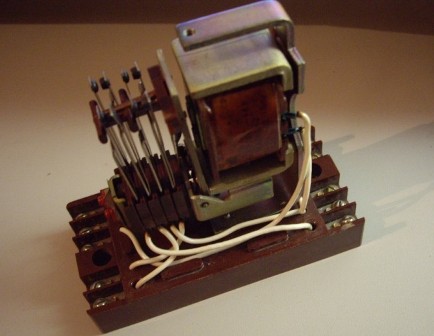
The photo shows the MKU-48 relay, in the lower part of which there is a coil connected by wires to the terminals. In the upper part you see a set of conductive plates in the contact group.
The coil is wound on a frame, a magnetic circuit is located in it. The coil is mounted on it by various methods, for example, due to a copper plate, a shaped plate, copper and insulating washers.
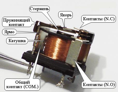
There can be a great many relay designs, but the main responsible nodes are the same:
1. The coil.
2. Contact groups.
Their relative position, the trajectory of movement, their number can vary significantly.
Problem 1 - Contacts
Perhaps in the first place in the problem of the functioning of all switching devices is carbon deposits or wear contacts. To increase durability and reduce contact resistance, they can be coated with expensive metals such as silver, gold or platinum.
But the resources of all mechanical parts are limited by the number of operations. In addition to the shock load that occurs when they are closed, the contacts are destroyed by sparks and arcs, which will certainly be formed when at least some powerful electrical circuits are turned on, especially if they contain inductance or capacitance.
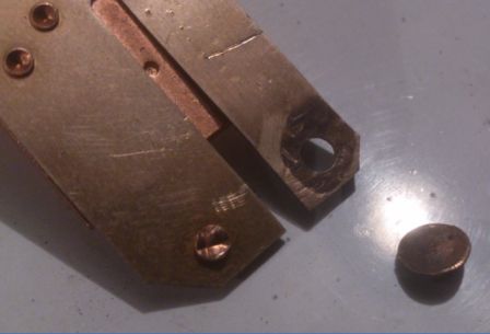
Surely you noticed that when you plug the charger from a smartphone or laptop into a wall outlet, a sheaf of sparks pops up, and so this is the process of charging the input capacity. From such outbreaks, carbon deposits are formed at the contacts.
If in the outlet, thanks to its design, it is not so scary - because you, by inserting and removing the plug, clean off a small part of the soot, then the deposit accumulates in the relay, sooner or later the resistance of the contacts increases, they begin to heat up more strongly, hence even more deposits.
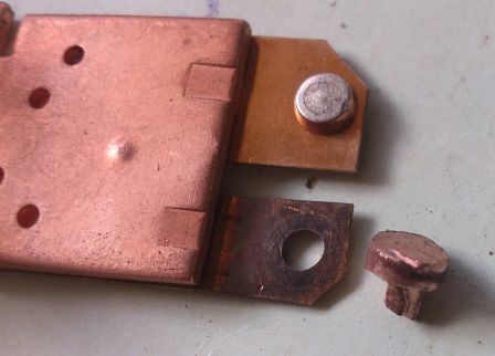
The next stage is either burnout of the contact plates or parts of the relay case (automatic machine, starter ...), or, in the best case, the current simply stops flowing through the relay.
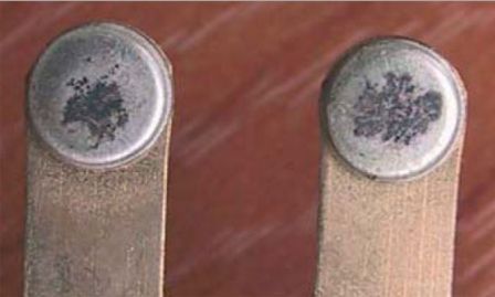
In this case, you need to restore contacts. In the simplest cases, you need to brush them with an eraser. In general, the contacts are cleaned with alcohol with a toothbrush, or with a cotton swab, or with a piece of paper moistened with alcohol, if the distance between the contacts is small, and after drying, they are ground with suede. After that, it is worth strengthening the contact clamp if it has loosened and if there is a possibility of adjustment.
But, if they are burnt hard enough, but there is nothing to replace, you can clean them with glass paper or fine sandpaper. Only the durability of such a repair depends on the residual condition of the contacts.
Here you need to clean the soot and align the contact pad, while not leaving scratches and not removing the metal layer.In this case, the contact planes should, when they are closed, be as close to each other as possible. The contact resistance depends on the contact resistance and heating of the contacts with the passage of current.
Problem 2 - Coil
The magnetic flux that occurs around the coil captures the surrounding space and relay mechanisms, the movement of the armature and the operation of the contacts. This will not happen if the coil burns out. Let's look at common problems with the electromagnetic relay system.
1. Open wire winding at the junction (soldering) with the terminal. It occurs due to vibrations, increased value of current in the coil, corrosion and oxidation.
2. Inter-turn closure. With such a malfunction, increased heating of the coil, poor tightening of the armature and clamp of contacts, increased hum (due to increased current), and vibration of the case are characteristic.
3. A wire break in the coil itself.
Symptoms
We examined the main causes of failure of the relay. There are not so many of them. However, the symptoms of these malfunctions are greater. To correctly diagnose and solve the problem, you need to understand their cause. Let’s now talk about how they manifest in practice.
Why the relay is buzzing loudly
The inter-turn circuit is a local damage to the insulation of the coil winding wire and the passage of current directly through some part of the turns. Those. the current does not flow along the length of the coil, but at a point, from one mass of the conductor to another. The current in this case may increase.
Then the relay does not work in the nominal mode, the magnetic flux can deviate from the required value to a greater or lesser extent, this causes instability of the position of the armature, vibration in the magnetic circuit, lined iron. This defect is especially noticeable on alternating current relays, which always buzz slightly, then with a similar problem they begin to vibrate strongly, and their hum rises at times.
Outwardly, this can manifest itself as darkening in individual parts of the coil. Further operation of the relay with such a defect will lead to the fact that in the place of the inter-turn circuit there will be increased heating, over time the coil will cease to function, there are two options for the development of the situation:
1. Good - part of the turns will burn out in the coil, and the circuit will be broken, the current will cease to flow from the resulting burnout. Then the magnetic circuit and the chassis of the coil will remain intact. In this case, it is enough to find the same coil and replace it. For this, the relay is not completely disassembled, but only in those places where it is necessary, for example, in the RPM, the coil is removed from the chassis and replaced without any problems.
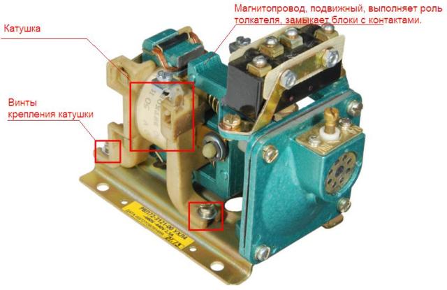
2. The bad option - the relay heats up and from high temperature ignition of the windings and insulators occurs, resulting in damage to the magnetic circuit. If it is movable, as in the photo above, then its further work may be impaired or impossible at all, then in addition to the coil you need to find the magnetic circuit, in which case it is easier to change the relay completely and leave the burned out for spare parts if the contact groups in it have survived.
In addition to the relay itself, this can lead to further problems in the form of a fire. Therefore, if the relay began to buzz strongly - do not postpone its inspection for later.
The coil can be rewound, the wrapping data can be indicated on the label that surrounds the coil. In the photo below you see what information can be indicated:
-
Wire mark;
-
Wire diameter;
-
The number of turns;
-
Working voltage;
-
Frequency.
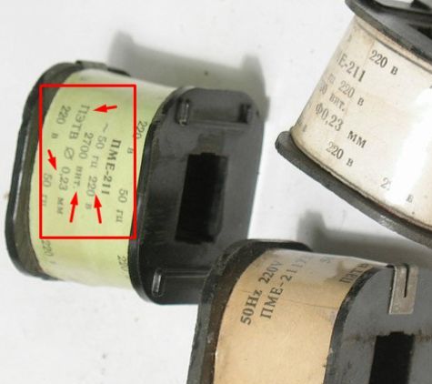
Now you need to remove the label and see: can damage lurk on the surface? Then you can rewind a little wire, fix the problem (insulate and solder) and stomp back. If no defects are visible on the surface, then you need to cut or rewind the entire winding to look for a malfunction. If it is substantial - rewind with a new wire.
If such a label is burned out or damaged, you should try to install the relay on the winding machine and unwind it manually by counting the number of turns.
Cracking relay
The relay can crack with a poor contact clamp, there are three reasons for this problem:
1. Wear of contacts.
2. Adjustment of a pressure plate.
3. Insufficient coil current.
The first two problems are more mechanical in origin. If the contacts are worn out, they can spark and crack. Then they need to be replaced. If there is nothing to replace, you can try to polish and level them.
It is necessary to achieve that the contact area is not less than 2/3 of the total area, in order to verify this, take carbon paper and apply it to plain paper, after which they make a contact imprint.
The tension (the elasticity of the plates on which the contacts are located) is checked by a dynamometer (in theory), in practice, they simply bend the contact and see how it came back, if it was bent slightly, and returned sluggishly, then adjustment is necessary. If you leaned back tight, and returned with a click - then everything is fine.
If the coil current a small relay will also crack. The fact is that then the magnetic field is weak and the clamping force at the contacts, too. The coil current may be low due to voltage drops, as well as wiring problems. There may be a connection loss somewhere, inspect all connections and terminals.
The relay sticks
You disconnected the circuit, and the relay remained in the active position, and this happens every other time, i.e. the problem is not sustainable:
There can be three reasons:
1. Bad contact.
2. Environmental impact
3. Mechanical failure.
4. Problems in wiring.
The poor condition of the contacts, as I have repeatedly said, is the reason for heating, and so heating can cause the contacts to stick. The contacts are heated to such an extent that the metal surface sticks together.
Check the purity of the relay case, and that some living creature may have settled inside it, or it has been flooded with something. It is likely the natural origin of the problem, the type of spider nest in the electrical panel or something like that.
If the relay case is somewhat sticky, then check if this substance is inside, maybe this is the reason for the contacts sticking. Well, the last "natural" option - maybe it froze?
Check the voltage at the relay contacts, maybe there is a leak somewhere, and the relay remains energized and its contacts do not disconnect.
Relay does not work
Coil winding is made of thin copper enameled wire. The thickness of the wire can be in the region of 0.07 mm and above. The power of switching on the relay and the current necessary to close the contacts depend on the thickness of the wire and the length of the winding.
To connect the relay to other devices, terminals or other types of contacts are located on its lower part (often, but not necessarily on the lower). The simplest problem is when one of the ends of the coil is soldered from this terminal.
In this case, just solder the end of the coil. Be careful when you strip the wire from enamel, you can break it, and it will fall off soon.
Perhaps the relay does not work, because the coil is broken. The cliff can be on the surface, or maybe in the middle, then the procedure is the same as in the case of inter-turn:
1. Pull out the reel.
2. Remove the shell from it.
3. Check for a break on the surface, if not unwind, search inside.
4. Solder the cliff and insulate.
5. Reassemble the coil.
Relay test
A quick relay test can be performed by dialing or a multimeter. To do this, ring the coil contacts, the circuit must be closed, if the ringing does not work, it means that the coil is not open.
The next step is to check the normally-closed contacts, when there is no voltage on the relay, they should be closed, the resistance should tend to zero, and the continuity should work. Apply voltage to the winding and check also the normally open pair. She must close.
A more accurate check can be done with a megger.It is necessary to ring the resistance between independent groups of contacts, it must be large, specifically, how much is written in the technical characteristics of the switching device, generally from 1 MΩ or higher. Also check the resistance between the coil and the magnetic circuit, the anchor. It should also be big. Otherwise, the relay will not function correctly.
See also at i.electricianexp.com
:
