Categories: Practical Electronics, Electrician Secrets
Number of views: 108971
Comments on the article: 0
Single-phase induction motor control device
 The proposed device can be used to control single-phase asynchronous motors, in particular, for starting and braking an asynchronous motor (HELL) with a short-circuited rotor of low power, having a starting winding or starting capacitor, disconnected before the end of the start. It is possible to use the device to start more powerful asynchronous motors, as well as to start three-phase motors operating in single-phase mode.
In the known device [1], a normal restart is possible only after cooling of the thermistor and the braking mode of the robot is not provided. The proposed device has wider functionality.
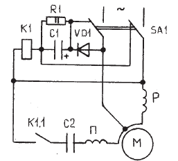
The device (Fig. 1) contains a two-pole switch SA1 for two positions, with the help of which the working winding P of the induction motor and the winding of the electromagnetic relay K1 are connected through the rectifier diode VD1, a timing RC circuit consisting of a parallel connected resistor R1 and an electrolytic capacitor C1. The closing contact K1.1 relay K1 is used to connect the starting winding II HELL to the mains through the phase-shifting element C2 and switch SA1.
In the initial prestart position, the coil of the electromagnetic relay K1 and the rectifier diode VD1 are bridged by the contacts of the switch SA1. The timing RC circuit through the same switch contacts is connected to the terminals of the working winding R.

The device operates as follows.
When the ABP is turned on with the help of a two-pole switch SA1, the working winding P flows around the current and relay K1 is triggered by the circuit: diode VD1, timing RC circuit, relay coil K1, switch SA1. Relay K1 by contact K1.1 connects the starting winding P to the network with a phase-shifting element C2. After a period of time determined by the RC timing circuit, the diode VD1 is closed by this circuit and the relay opens its contact K1.1 in the starting winding circuit P, disconnect it from the network. Start HELL is over. Capacitor C1 is charged during the entire operating time of the HELL, almost to the amplitude value of the mains voltage. The voltage on it can be slightly reduced by reducing the value of the resistor R1. When the AD is disconnected from the network, the diode VD1 and the motor working winding P are shunted by the switch SA1, and the timing RC circuit is connected via the switch to the terminals of the working winding. The capacitor of the time-conducting RC chain is discharged to the working winding P, creating a braking torque on the motor shaft. Restarting is possible immediately after stopping blood pressure, because RC chain capacitor discharged. HELL braking time up to 1 s with free run-out of the HELL rotor.
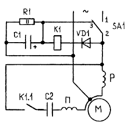
A simplified version of the device is shown in Fig. 2. This option was used by the author for several years for the AM of the refrigerator refrigeration unit, in which the starting winding was “tinged” due to a large excess of voltage in the network, as a result of which the starting relay of the refrigerator did not turn off the starting winding of the AD and it overheated. At the same time, the braking circuit (contacts 2-3 of the SA1 switch) was not used due to uselessness, and contacts 1-2 were replaced by the contacts of the refrigerator thermal relay.

Details Any switch suitable for current and voltage is used as switch SA1. Diode VD1 type D226B can be replaced by D237B, D237V or KD105 with any letter index. Resistor R1 type MLT-2 50 ... 100 kOhm. Capacitor C1 - electrolytic type KE-2 at 30 uF and 450 V can be replaced by KE-1 or EM. The latter is small-sized. Electromagnetic relay K1 intermediate relay AC 220 V type RP-21, RP-25 or MKU-48.Capacitor C2 is selected based on the calculation of 7 microfarads per 100 watts of power of the HELL type MBGO-2 for a voltage of at least 400 V or type MBHCH, which is preferable.
The device does not consume electricity during operation of the induction motor, does not require adjustment and starts to work immediately with serviceable elements and proper installation.
See also at i.electricianexp.com
:
