Categories: Featured Articles » Practical Electronics
Number of views: 68633
Comments on the article: 8
How to protect against voltage fluctuations
 Description of a simple device that disconnects the load if the mains voltage goes beyond acceptable limits.
The tolerance for the mains voltage for powering household electronic and just electrical equipment is plus or minus 10%. But in the conditions of the domestic energy supply system, this requirement is often not complied with.
The voltage can be significantly too high or much lower than normal, which can lead to equipment failure. To prevent this from happening, the article describes a simple device that will disconnect the load on time before it has time to burn out.
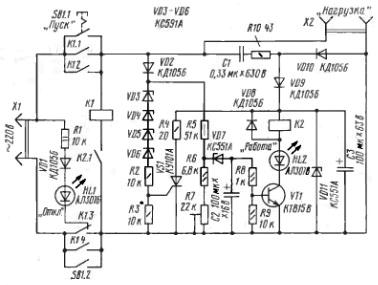
A diagram of a fairly simple protection device is shown in Figure 1.
Operating principle. Circuit description
Disconnecting the load from the network occurs when the voltage exceeds 242 V or becomes lower than 170 V. A powerful relay at the output of the device allows switching currents up to ten amperes, which allows you to connect a load with a capacity of up to two kilowatts.
In the initial state, the relay contacts are in the position indicated in the diagram. Switching contact K1.3 connects the HL1 LED to the network, signaling that the load is off, and that there is voltage in the network. The load is connected to the network by briefly pressing the SB1 "Start" button.
Figure 1. Protection against voltage fluctuations
The mains voltage through the quenching capacitor C1 and the resistor R10 is supplied to the rectifier diodes VD9, VD10, and charges the capacitor C3. The voltage on this capacitor is stabilized by a Zener diode VD11. From this rectifier, a low-power relay K2 is supplied, which controls the operation of a powerful relay K1, which switches the load itself.
Through the diode VD2, the mains voltage is supplied to the switching unit of the relay K2. If the voltage in the network is more than 170 V, the Zener diode VD7 will open, which will allow the capacitor C2 to be charged to a voltage sufficient to open the transistor VT1, which will turn on the low-power relay K2. (A VD8 diode is connected in parallel to the coil of relay K2. Its purpose is to protect the transistor from the self-induction EMF that occurs when relay K2 is turned off.)
This relay with its contact K2.1 will turn on the powerful relay K1, and with its contacts K1.1 ... K1.4 it will supply the mains voltage to the load. The "Start" button can now be released, the device has entered the operating mode. At the same time, the HL2 LED lights up, signaling the normal operation of the device. HL1 LED will turn off, the device has entered the operating mode.
Undervoltage protection
If the mains voltage becomes less than 170 V, the Zener diode VD7 will close, and the charging of the capacitor C2 will stop. This will lead to the fact that the capacitor C2 is discharged through the resistor R8 and the transition base - emitter of the transistor VT1. The transistor will close and intermediate relay K2 will disconnect and contact K2.1 will turn off the powerful relay K1 - the load will be de-energized.
Over Voltage Protection
The overvoltage protection assembly is assembled on the thyristor VS1. It works as follows.
The mains voltage, or rather its positive half-wave, is supplied through the VD2 diode to the Zener diodes VD3 ... VD6 connected in series, and through them to the resistors R2 and R3 connected in series. If the mains voltage rises above 242 V, the zener diodes will open and a voltage drop will be created on resistor R3, the value of which will be sufficient to open the thyristor VS1.
An open thyristor through a resistor R5 will "put" the voltage across the capacitor C3. (Since the rectifier supplying this capacitor is assembled according to the circuit with a quenching capacitor, it is not afraid of even short circuits.Resistor R4 is needed only so that the thyristor VS1 is not burned by the discharge of capacitor C3.) This voltage will not be enough to hold relay K2, it will turn off, and relay K1 will turn off with it, and the load will be disconnected. The device itself will also be de-energized, except for the chains R1, VD1, HL1.
Re-enable the load can only be done by pressing the "Start" button. In this case, one should not rush, but wait a while, because sometimes, when the power is restored, quite large drops occur, you can even say surges, voltages.
A few words about the details
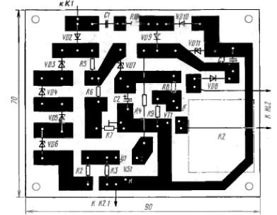
Almost all parts of the device are mounted on a printed circuit board made of foil fiberglass with a thickness of 1.5 ... 2 mm. The topology of the board is so simple that you can just cut it with a sharp knife. Almost all the details are located on the board. The board with the parts located on it is shown in Figure 2.
Figure 2. Design of the circuit board of the surge protection device
The entire device as a whole must be placed in a housing made of insulating material. Those parts that did not fit on the board are installed inside the case by the method of surface mounting. If a powerful relay will have significant dimensions, then it should also be placed outside the board.
As a powerful relay K1, it is possible to use relays of types MKU-48, RPU-2 or similar with a coil for an alternating voltage of 220 V. As relay K2, you can use relays RES-6, RES-22 or another type with a response voltage of about 50 V and coil current no more than 15 mA. This relay can have only one contact.
When installing the device, you can apply the following types of parts: fixed resistors type MLT, trimming resistor type SP3-3 or SP3-19. Capacitor C1 of type K73-17 for operating voltage not lower than indicated on the diagram, oxide capacitors of type K50-35 or imported. As diodes VD1, VD2, VD8 ... VD10, any low-power diodes with a reverse voltage of at least 400 V, as well as imported type 1N4007, are suitable.
Transistor VT1 can be replaced by KT817G, KT603A, B or KT630D.
The increased voltage of the network at which the shutdown is performed is determined by the stabilization voltage of the Zener diodes VD3 ... VD6, which, instead of those indicated on the diagram, it is possible to use Zener diodes KS600A, KS620A, KS630A, KS650A, KS680A.
With their help, a rough adjustment of the shutdown threshold is made, and a smoother one is carried out by selecting a resistor R3. It is easiest to set up a variable resistor with a resistance of about 10 kilograms instead of it, and at the end of the setting, replace it with a constant, equal to the resistance of the input part of the variable resistor.
The lower threshold (minimum voltage) is set using the trimmer resistor R7.
Setting up a device is most easily done using LATR. First set the upper threshold. To do this, connect the device to the LATR, and gradually increase the voltage, of course, controlling it with a voltmeter. By selecting the Zener diodes VD3 ... VD6 and resistor R3, the device must be turned off at a voltage of 242 V. The device - the consumer, of course, should not be connected. To prevent the device from triggering on the lower threshold, set the engine of the tuning resistor R7 to the upper position according to the scheme.
After setting the upper threshold, you should use the resistor R7 to turn off the device when the voltage is reduced to 170 V.
If the possibility of forced shutdown of the device is required, then a button with an open contact can be set in series with the relay contact K2.1.
Safety notes
The design does not have galvanic isolation with the supply network, therefore, when setting it up, one must be extremely careful and careful, follow all safety rules when working in electrical installations. It is best to use a safety transformer for commissioning: LATR should be connected after it.Then the setting can be done without any fear.
Boris Aladyshkin
See also at bgv.electricianexp.com
:


