Categories: Interesting Facts, Novice electricians
Number of views: 97676
Comments on the article: 4
Hall effect and sensors based on it
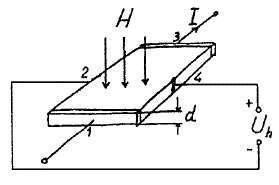
 The Hall effect was discovered in 1879 by the American scientist Edwin Herbert Hall. Its essence is as follows (see. Figure). If a current is passed through a conductive plate and a magnetic field is directed perpendicular to the plate, then the voltage appears in the direction transverse to the current (and the direction of the magnetic field): Uh = (RhHlsinw) / d, where Rh is the Hall coefficient, which depends on the material of the conductor; H is the magnetic field strength; I is the current in the conductor; w is the angle between the direction of the current and the magnetic field induction vector (if w = 90 °, sinw = 1); d is the thickness of the material.
Due to the fact that the output effect is determined by the product of two quantities (H and I), Hall sensors are very widely used. The table shows the Hall coefficients for various metals and alloys. Designations: Т - temperature; B is the magnetic flux; Rh - Hall coefficient in units of m3 / C.
Hall-effect proximity switches based on the Hall effect have been used abroad quite widely since the beginning of the 70s. The advantages of this switch are high reliability and durability, small dimensions, and the disadvantages are constant energy consumption and a relatively high cost.

The principle of operation of the Hall generatora
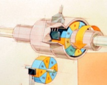
The Hall sensor has a slotted design. A semiconductor is located on one side of the slot, through which current flows when the ignition is turned on, and on the other hand, a permanent magnet.
In a magnetic field, moving electrons are affected by a force. The force vector is perpendicular to the direction of both the magnetic and electric components of the field.
If a semiconductor wafer (for example, from indium arsenide or indium antimonide) is introduced into a magnetic field through induction into an electric current, then a potential difference arises on the sides, perpendicular to the direction of the current. Hall voltage (Hall EMF) is proportional to current and magnetic induction.
There is a gap between the plate and the magnet. In the gap of the sensor is a steel screen. When there is no screen in the gap, a magnetic field acts on the semiconductor plate and the potential difference is removed from it. If there is a screen in the gap, then the magnetic lines of force close through the screen and do not act on the plate, in this case, the potential difference does not occur on the plate.
The integrated circuit converts the potential difference created on the plate into negative voltage pulses of a certain value at the output of the sensor. When the screen is in the gap of the sensor, there will be voltage at its output; if there is no screen in the gap of the sensor, then the voltage at the sensor output is close to zero.

Fractional quantum Hall effect
Much has been written about the Hall effect, this effect is used extensively in technology, but scientists continue to study it. In 1980, the German physicist Klaus von Klitzung studied the operation of the Hall effect at ultralow temperatures. In a thin semiconductor plate, von Klitzung gradually changed the magnetic field strength and found that the Hall resistance does not change smoothly, but in jumps. The magnitude of the jump did not depend on the properties of the material, but was a combination of fundamental physical constants divided by a constant number. It turned out that the laws of quantum mechanics somehow changed the nature of the Hall effect. This phenomenon has been called the integral quantum Hall effect. For this discovery, von Klitzung received the Nobel Prize in Physics in 1985.
Two years after the discovery of von Klitzung in the Bell Telephone laboratory (the one in which the transistor was opened), the Stormer and Tsui employees studied the quantum Hall effect using an exceptionally clean sample of large gallium arsenide made in the same laboratory.The sample had such a high degree of purity that the electrons passed it from end to end without encountering obstacles. The Stormer and Tsui experiment took place at a much lower temperature (almost absolute zero) and with more powerful magnetic fields than in the von Klitzung experiment (a million times more than Earth's magnetic field).
To their great surprise, Stormer and Tsui found a jump in Hall resistance three times greater than that of von Klitzung. Then they discovered even greater leaps. The result was the same combination of physical constants, but divided not by an integer, but by a fractional number. Physicists charge an electron as a constant that cannot be divided into parts. And in this experiment, as it were, particles with fractional charges participated. The effect was called the fractional quantum Hall effect.

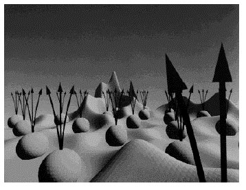
A year after this discovery, an employee of the La Flin laboratory gave a theoretical explanation of the effect. He stated that the combination of ultra-low temperature and a powerful magnetic field causes the electrons to form an incompressible quantum fluid. But the figure using computer graphics shows the flow of electrons (balls) piercing the plane. Roughnesses in the plane represent the charge distribution of one of the electrons in the presence of a magnetic field and the charge of other electrons. If an electron is added to a quantum liquid, then a certain amount of quasiparticles with a fractional charge is formed (in the figure this is shown as a set of arrows for each electron).
In 1998, Horst Stormer, Daniel Tsui, and Robert Laughlin were awarded the Nobel Prize in Physics. Currently, H. Stormer is a professor of physics at Columbia University, D. Tsui is a professor at Princeton University, and R. Laughlin is a professor at Stanford University.
Metal (alloy)
T, ° C
B, T
R, mj/ k
Aluminum
-190
0,54
-0,22
0
0,54
-0,33
+300
0,54
-0,39
+600
0,54
-0,41
Gold
-190
0,54
-0,715
0
0,54
-0,695
+300
0,54
-0,721
+600
0,54
-0,785
Silver
-190
0,54
-0,925
0
0,54
-0,909
+300
0,54
-0,949
+600
0,54
-1,002
Copper
-190
0,54
-0,56
0
0,54
-0,513
+300
0,54
-0,543
+600
0,54
-0,587
Iron
+26
0,3...1,7
+5,5
Cobalt
+ 100
0,1...1,6
+8,65
+300
0,1 ...1,6
+21,2
+460
0,1... 1,6
+89,4
+960
0,2... 1
+200
Antimony morgan
+20
0...2
+ 1200
+320
0...2
+10500
Chrome tellurium
0
0-1,6
-31500
See also at i.electricianexp.com
:
