Categories: Featured Articles » Novice electricians
Number of views: 20710
Comments on the article: 0
What is an ammeter, types, device and principle of operation
To determine the current value in an electric circuit, special devices are used - ammeters. The ammeter is connected in series to the circuit under study, and, due to the extremely small intrinsic resistance, this measuring device does not make any significant changes to the electrical parameters of the circuit.
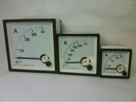
The instrument scale is graduated in amperes, kiloamperes, milliamperes, or microamperes. To extend the measurement range, the ammeter can be connected to the circuit through a transformer or parallel to the shunt, when only a small fraction measured current passes through the device, and the main circuit current flows through the shunt.
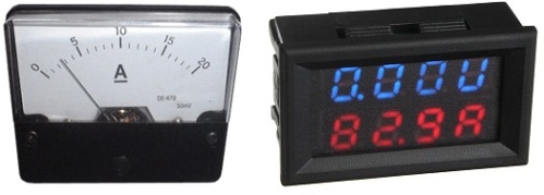
Today, there are two particularly popular types of ammeters - mechanical ammeters - magnetoelectric and electrodynamic, and electronic - linear and transformer.
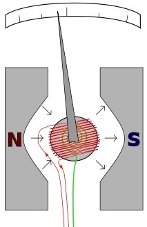
In a classical magnetoelectric ammeter with an arrow and a graduated scale, a certain part of the measured current passes through the moving coil of the device, inversely proportional to the resistance of the coil, connected in parallel with a calibrated shunt of low resistance.
The current (direct or rectified) passing through the coil leads to rotation of the needle of the magnetoelectric ammeter, and the angle of the arrow is proportional to the magnitude of the measured current.
The current through the coil of the ammeter creates a torque on it due to the interaction of its own magnetic field with the magnetic field of a stationary stationary permanent magnet. And since the arrow is connected to the coil-frame, it tilts to the appropriate angle and indicates the current value on the scale.
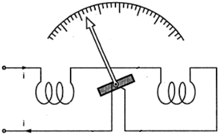
The electrodynamic ammeter is arranged in a slightly more complex way. It has two coils - one motionless, and the second - movable. Coils are interconnected in series or in parallel. When currents pass through the coils, their magnetic fields interact, as a result, the movable coil to which the arrow is connected deviates by an angle proportional to the magnitude of the measured current.
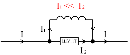
In devices designed to measure significant currents, the main current always passes through a shunt of low resistance, and the coil connected to the arrow takes on only a small fraction of the current, acting as a conductive branch from the main current path. The ratios of currents through the measuring frame and through the shunt are usually taken as: 1 to 1000, 1 to 100, or 1 to 10.
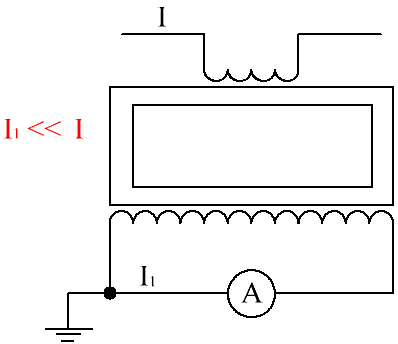
Often, for measuring significant currents or when working with high-voltage circuits, the inclusion of an ammeter through a measuring current transformer is used. In this case, a current proportional to the current in the primary winding is measured in the secondary winding, and the scale is graduated according to the current measured in the primary winding. The secondary winding of the current measuring transformer is always shunted by a resistor, otherwise the emf induced on it could be dangerously high.
When a measuring current transformer is connected to a high voltage circuit, the ammeter case and the secondary circuit of the measuring transformer must be earthed in order to be safe in case of insulation breakdown.
See also on this topic: Features of connecting ammeters in DC and AC circuits
Based on current transformers or Hall sensors Ammeter type "current clamp". The use of a Hall sensor makes it possible to measure direct current, and current transformers - to measure alternating current.
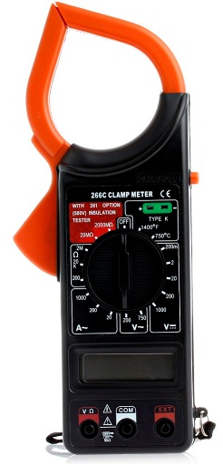
Current Transformer Pliers - for measuring alternating current, - easier to manufacture and they are cheaper.The detachable magnetic core is the core of a current transformer, on which a secondary winding shunted by a resistor is wound. The primary winding is the wire, which is clamped around with clamps to measure the current in it.
The electronic circuit calculates in accordance with Ohm's law, based on the voltage on the shunt resistor and the transformation coefficient, the current in the circuit under study.
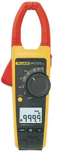
UNI-T UTM 1202A Clamp Meter:
Ticks based on Hall sensor (for measuring direct current) use the Hall effect when the magnetic field created by direct current leads to the appearance of a proportional Hall EMF in the sensor circuit.
The advantage of current clamps with a Hall sensor is that they have high speed and allow you to track short-term inrush currents.
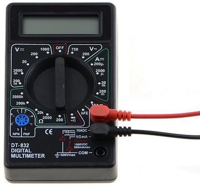
Finally in simple digital multimeters with current measurement function, a linear measurement circuit with a shunt is applied. There is no moving frame with an arrow; instead, the electronics measures the voltage drop across the shunt of a known resistance, compares it with a reference value, and calculates the current value. The result of the current measurement is displayed on a digital display.
See also at i.electricianexp.com
:
