Categories: Electrician at home, Sockets and switches, Electric installation work
Number of views: 24815
Comments on the article: 5

How to connect the neutral protective conductor to outlets
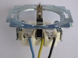
 

How to connect the neutral protective conductor to outletsThe current rules for the installation of electrical installations impose increased requirements on the reliability of the connection of protective neutral wires and the electrical contacts created by them. In this case, the connection of electrical appliances should be done through a branch, and not a cable.

To understand the difference between these methods, imagine a fruit tree with a grafted branch. Branches that have grown naturally and extend from the trunk can be considered as one with the tree. The term branching is suitable for them, and the scion is created artificially - this is a train. Under a loop in the energy sector, it is customary to consider a piece of wire connected to an electrical wiring to create a specific electrical circuit.

In other words, the PUE requirement can be explained as follows: the zero conductor protector must be intact throughout its length, which means a ban not only on its creation from separate pieces of wire that are connected in a certain way, but also the connection of additional conductors to it for switching other power consumers.

This requirement is explained simply: when an emergency current appears in a socket or device connected to it, a dangerous potential will flow through the protective conductor, the energy of which can destroy an unreliable connection. In this case, all devices connected to the loop are left without a protective conductor.

Sometimes, electricians make a mistake when wiring, when they tie part of the sockets with one PE conductor without breaking it. To do this, insulation is removed from a small section of the wire, and the metal core is rolled up and clamped under the screw. After that, the free end of the wire goes to the next outlet. This method is not considered a branch and cannot be used.
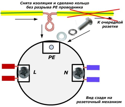
Option to connect the PE conductor to the outlet

Connection option PE conductor to outlet

To connect the PE conductor to sockets, it is necessary to use branches to make branches from the protective zero line through the installation box. To connect to it, it is recommended to use special connectorsmanufactured by Wago, Went or Scotchlok. It should be noted that for some electricians the designs of the first two companies are in doubt. Scotchlok clamps for mortise contact have proven their best.

This method involves connecting the sockets to a protective zero by branching, and to the phase and working zero by a loop. It is shown in the figure below. For convenience of perception, gaps of zero and phase are not shown on it.
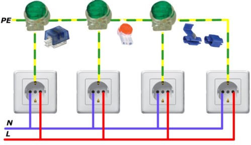
Wiring diagram for a PE conductor to a Scotchlok socket

Wiring diagrams PE conductor to outlet by Scotchlok connector

The connector itself is small, it can be hidden directly in the installation box of the outlet. The wire connection will look something like this.
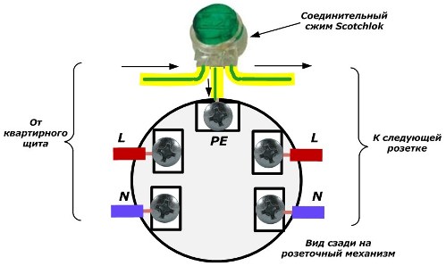
Connecting a PE conductor to a socket with a compression clamp

Connection PE conductor to outlet

To install the connector, it is necessary to provide the amount of free space between the bottom of the installation box and the socket mechanism. It should be equal to or slightly greater than the thickness of the compression with the wires connected.
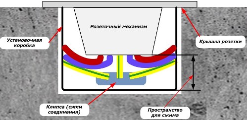
Installation of a socket with a PE conductor connecting device

Installation of a socket with a connection PE conductor connecting device

There is another way to switch the neutral protective conductor to outlets using an additional branch box. It is recommended to install it near plug-in sockets.


A PE conductor from the apartment board is connected to the box and all wires are connected to it branch welding. It is also allowed to use the factory-made terminal blocks in the box.

Such an installation diagram is shown in the figure.
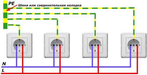
Wiring diagram for PE conductor to socket via bus

Wiring diagram PE conductor to the outlet via bus

It also does not show gaps created in the phase and working zero conductors.

See also at i.electricianexp.com:

  • How to install a block of electrical switches with a socket
  • Schematic and wiring diagrams of lighting in an apartment and a house
  • How to determine the ground wire
  • How to connect a cooker hood to an electrical network
  • What is the danger of self-grounding in the apartment (alteration TN-C ...

  •  
     
    Comments:

    # 1 wrote: | [quote]


    In other words, the PUE requirement can be explained as follows: the zero conductor protector must be intact throughout its entire length ...

    In my opinion, only the first and last circuits satisfy this requirement, and the "Scotchlok connector wiring diagram for connecting a PE conductor to a socket" does not. Why then is it forbidden to do the first and allowed the second?

     
    Comments:

    # 2 wrote: Igor | [quote]


    In the diagrams, the phase wire is connected to the right pin of the socket. And on all euro plugs the phase is indicated on the left contact. How to connect the phase in the euro outlet?

     
    Comments:

    # 3 wrote: | [quote]


    "... which means a ban not only on its creation from separate pieces of wire that are connected in a certain way ..."
    However, on the 2nd and 3rd scheme, we see exactly this. On the 2nd diagram, pieces of grounding wire are connected in a certain way - using a clamp, and on the 3rd diagram through the bus - also in a certain way. Thus, only the 1st scheme meets the specified requirement, which the author called incorrect (maybe it is - I do not argue). In general, it’s difficult for me to imagine a branch inside an apartment, a house without violating the integrity of the main wire, if this is not the end of the line and there is 1 socket on it.
    P. S. Of course, I am just learning and maybe I’m not catching up with something ...

     
    Comments:

    # 4 wrote: | [quote]


    The first and second schemes for connecting outlets are absolutely identical when using a high-quality connector in the second case. And they are used at relatively small distances from each other for specific outlets when connecting low-power consumers. These schemes are similar to the design of a conventional household electric extension cord. The latter scheme is valid when connecting powerful consumers, because in the event of a breakdown on the housing in one of the devices, a significant potential is created on the grounding conductor and, if you touch the metal housing of another inoperative device connected to another outlet and to a metal water pipe, there may be consequences. The latter scheme is also used to connect individual apartments to the access electrical panel. For intra-apartment wiring at currents consumed by devices up to 16-20 amperes, it makes sense to use it exclusively on aluminum wires, and even then with a "big stretch" ...

     
    Comments:

    # 5 wrote: MaksimovM | [quote]


    Igor, in a household single-phase network, there is no need to observe the location of the phase and zero terminals in outlets. In this case, the main thing is to connect the phase and neutral conductor exactly to the terminals intended for this purpose in the socket or plug, without confusing them with the grounding contact.

    As for the first scheme, the commentators above are wrong. If the conductor is not broken, then there are no contact connections, that is, the requirement that the protective conductor is inextricable is observed. But this method of connecting outlets is prohibited, since in the event of damage in one of the outlets, subsequent outlets, the protective wire of which is connected from the damaged outlet with a loop, will remain without a protective conductor.

    As for the option of branching the protective conductor through the use of various connectors, this method also does not provide sufficient reliability. Connectors also cannot provide conductor continuity requirements. For example, if the contact connection on the first branch is broken in the second scheme in the article, then subsequent sockets will also remain without a protective conductor.